Electrical Circuit Fundamentals
advertisement

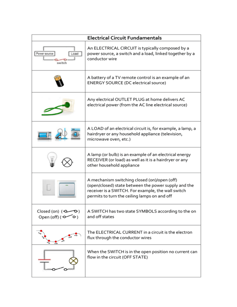
Electrical Circuit Fundamentals An ELECTRICAL CIRCUIT is typically composed by a power source, a switch and a load, linked together by a conductor wire A battery of a TV remote control is an example of an ENERGY SOURCE (DC electrical source) Any electrical OUTLET PLUG at home delivers AC electrical power (from the AC line electrical source) A LOAD of an electrical circuit is, for example, a lamp, a hairdryer or any household appliance (television, microwave oven, etc.) A lamp (or bulb) is an example of an electrical energy RECEIVER (or load) as well as it is a hairdryer or any other household appliance A mechanism switching closed (on)/open (off) (open/closed) state between the power supply and the receiver is a SWITCH. For example, the wall switch permits to turn the ceiling lamps on and off Closed (on) ( Open (off) ( ) ) A SWITCH has two state SYMBOLS according to the on and off states The ELECTRICAL CURRENT in a circuit is the electron flux through the conductor wires When the SWITCH is in the open position no current can flow in the circuit (OFF STATE) If it is in the CLOSED position the current may flow in the circuit (ON STATE). And if the circuit integrates a bulb as receiver, turning on the switch will light up the bulb The BULB intensity increases with the electric current INTENSITY. A standard lamp comprises a tungsten filament inside the glass bulb where the air was replaced with inert gases. This filament of tungsten conductive material is an electrical resistance The ELECTRICAL RESISTANCE (R) of an electrical conductor is the greater or smaller opposition offered to the flow of electric current through the conductor OHM’S LAW tells us that when a current (I) flows through a resistance (R), a voltage drop appears at its ends (U), U = RI The DISSIPATED POWER (P) in a resistor is given by the voltage drop through it (U) multiplied by the current (I) value that flows through it. That is why an oven heats up... The voltage drop (U) is expressed in Volt (V), the electrical current (I) in Ampere (A), the electrical resistance (R) in Ohm () and the dissipated power (P) in Watt (W). The BULB POWER is given by the product of the voltage drop (U) by the current value (I) The voltage supply applied to an electrical circuit is equal to the sum of voltage drops in all different elements in of the circuit. In a circuit with two identical bulbs (equal resistance) supplied by a battery (V), the voltage drop in each bulb will be Ub = ½ V SERIES CIRCUIT - In a two bulb series circuit, the voltage drop across each bulb (resistance) is proportional to each bulb resistance and the current through both bulbs is the same. SERIES CIRCUIT – If one of the bulbs is faulty the other bulb will not light up. The current through both bulbs is zero (OPEN CIRCUIT) PARALLEL CIRCUIT - In a two bulb parallel circuit, the voltage drop across each bulb (resistance) is the same. The total current (I) of the main circuit is the sum of the currents through each component (I1, I2). According to Ohm's law, the current in each branch will be greater the lower is its resistance PARALLEL CIRCUIT - If the resistance of one of the branches is zero the current will bypass the other branch and the other lamp will not light up (SHORT CIRCUIT).


