Product sheet PVM
advertisement

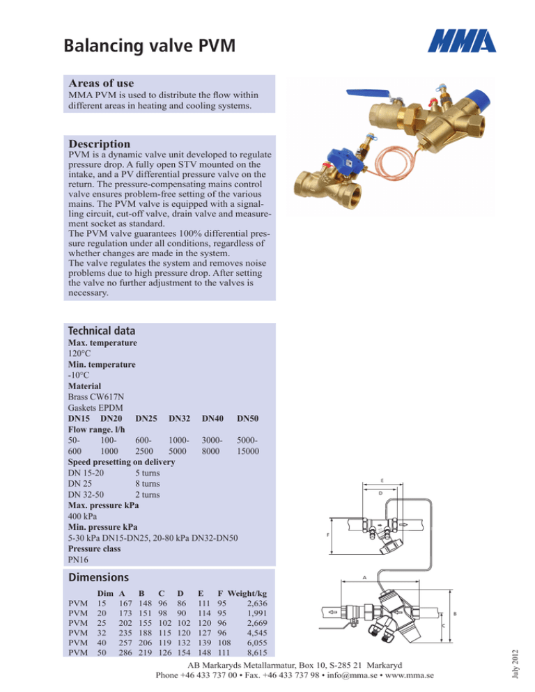
Balancing valve PVM Areas of use MMA PVM is used to distribute the flow within different areas in heating and cooling systems. Description PVM is a dynamic valve unit developed to regulate pressure drop. A fully open STV mounted on the intake, and a PV differential pressure valve on the return. The pressure-compensating mains control valve ensures problem-free setting of the various mains. The PVM valve is equipped with a signalling circuit, cut-off valve, drain valve and measurement socket as standard. The PVM valve guarantees 100% differential pressure regulation under all conditions, regardless of whether changes are made in the system. The valve regulates the system and removes noise problems due to high pressure drop. After setting the valve no further adjustment to the valves is necessary. Technical data Max. temperature 120°C Min. temperature -10°C Material Brass CW617N Gaskets EPDM DN15 DN20 DN25 DN32 DN40 DN50 Flow range. l/h 50- 100- 600- 1000- 3000- 5000600 1000 2500 5000 8000 15000 Speed presetting on delivery DN 15-20 5 turns DN 25 8 turns DN 32-50 2 turns Max. pressure kPa 400 kPa Min. pressure kPa 5-30 kPa DN15-DN25, 20-80 kPa DN32-DN50 Pressure class PN16 Dimensions PVM PVM PVM PVM PVM PVM D 25 DN 20 PN F 44 C 50 A Dim ABCDEF Weight/kg 15 167 148 96 86 111 95 2,636 20 173 151 98 90 114 95 1,991 25 202 155 102 102 120 96 2,669 32 235 188 115 120 127 96 4,545 40 257 206 119 132 139 108 6,055 50 286 219 126 154 148 111 8,615 AB Markaryds Metallarmatur, Box 10, S-285 21 Markaryd Phone +46 433 737 00 • Fax. +46 433 737 98 • info@mma.se • www.mma.se B C July 2012 E Setting Higher p Lower The valve is easy to set on the knob using a 4 mm Allen key. The setting is read off the pressure drop diagram for each dimension. When presetting the valve, start by screwing the setting to minimum. Then open the valve to the required value according to the diagram. The STV valve is used solely for shutting off and flow measurement, it must not be set in any position other than open. Presetting The PVM valve is preset according to the diagram. The curves (the oblique lines that indicate the pressure in the main line) are shown in intervals of 5 kPa to make it simple to take a reading. The curves can be moved so that the valve setting can be produced if, for example, 12 kPa is selected in a pipe instead. Example: We decide to maintain 12 kPa differential pressure in the main at a flow of 500 l/h (500 l/h comes from the presetting on the radiators). From the point where 12 kPa cuts the horizontal line (flow 500 l/h) a vertical line is taken down to the x-axis. It is then easy to read off that the valve should be set at approx. 7 turns. The minimum pressure drop will then be 1.9 kPa over the valve. Total pressure drop: To dimension the pump it will be: P = Ps + Pv = 12 +1.9 = 13.9 kPa Also include the pipe pressure drop from the valve to the pump. The pump can subsequently be adjusted optimally by measuring the differential pressure from PF to P- ( P pump). To verify the secondary pressure drop calculated, it can be checked by measuring PF to P+ and the result should then be 12 kPa. Ordering codes RSK no. Art.no. Name Description 9001124 9001125 9001126 9001127 9001128 9001129 PVM DN15 PVM DN20 PVM DN25 PVM DN32 PVM DN40 PVM DN50 G15 int. thread G20 int. thread G25 int. thread G32 int. thread G40 int. thread G50 int. thread July 2012 We reserve the right to alter information without notice AB Markaryds Metallarmatur, Box 10, S-285 21 Markaryd Phone +46 433 737 00 • Fax. +46 433 737 98 • info@mma.se • www.mma.se p Installation example C 5044 C 5044 25 DN 20 PN 25 DN 20 PN C 5044 25 DN 20 PN C 5044 25 DN 20 PN C 5044 25 DN 20 PN C 5044 25 DN 20 PN Overview of a heating system with 5 staircases with 4 apartments on each one. The critical valve, defined as the valve with the lowest pressure drop as a rule of thumb this will be the valve positioned furthest away from the pump, is used to lower the pump pressure so that the valve achieves the correct pressure. The lowest possible pressure is then obtained in the system. See dimensioning pump pressure. The critical point PVM is fitted in the intake, the signal pipe is to be connected at the low pressure side of the STV valve. The valve can be fitted irrespective of whether it is a straight length of pipe. Bends, tubes etc. can be installed immediately after the valve. 1. Flush the system before fitting signal pipe. 2. Install t-pipe with measurement socket on the STV valve. 3. Install signal pipe on the t-pipe and flush to ensure that there is no air in the signal pipe. 4. Install the signal pipe on the PVM valve on the return pipe. 2 1 Pf 25 DN 20 PN 44 C 50 3 PP+ AB Markaryds Metallarmatur, Box 10, S-285 21 Markaryd Phone +46 433 737 00 • Fax. +46 433 737 98 • info@mma.se • www.mma.se July 2012 Standard application PSTV Dimensioning Selecting the right valve in an installation requires some data about the system. P pump available differential pressure from pump P load differential pressure for circulation P STVP pressure drop over valve fully open (diagram) P PVM pressure drop over the PVM valve (diagram) Example: Calculated value for a valve is 0.4 l/s. 50 kPa is available differential pressure for circulation P load 20 kPa is required for the main. 25 DN 20 PN 44 C 50 PPump PLast We find the minimum differential pressure required for the PVM valve to achieve minimum working pressure in the diagram. Two valves can deliver 0.4 l/s DN25 and DN32. PPVM Adjustment and measuring When adjusting, the differential pressure on the PVM valve is measured and adjusted to 10 kPa. At least one radiator valve needs to be slightly open. When measuring of the flow use the STV valve and a measuringtool. To be able to measure the flow may the STV valves wheel be set lower to have a higher differential pressure over the STV valve. Note that the differential pressure over the STV valve will not be to high so that the min differential pressure over the PVM valve will be to low and the PVM valve stop to regulate. After the measruing of the flow open the STV valve fully again. Pf 25 DN 20 PN 44 C 50 PL H Optimising pump pressure Lowering to minimum possible pump differential pressure is carried out by measuring at the PVM valve and obtaining at least 13.2 kPa, this is the pump’s lowest level at which the PVM can be regulated. PP+ kv-value the STV valve July 2012 NumberDN10DN15DN20DN25DN32DN40DN50 of turns 1 0,11 0,18 0,34 0,48 0,79 1,20 2,00 2 0,18 0,320,600,771,322,053,60 3 0,27 0,450,831,031,802,805,20 4 0,41 0,621,131,502,704,107,60 5 0,65 0,86 1,55 2,30 4,10 6,20 11,90 6 1,02 1,17 2,10 3,60 5,90 8,90 16,70 7 1,78 1,62 2,90 5,00 7,80 12,00 21,20 8 2,30 2,55 3,85 6,50 9,70 14,70 25,00 9 2,60 3,15 4,50 7,90 11,50 17,10 28,60 10 2,80 3,55 5,10 8,80 13,10 19,50 31,50 We reserve the right to alter information without notice AB Markaryds Metallarmatur, Box 10, S-285 21 Markaryd Phone +46 433 737 00 • Fax. +46 433 737 98 • info@mma.se • www.mma.se Last Pressure drop diagram PV, DN15 Flow l/s Flow L/h 0,083 300 0,056 200 0,028 100 0 0 30 kPa 400 25 kPa 0,111 1,9 20 kPa 500 15 kPa 0,139 Δp min PV valve 2,8 10 kPa 600 5 kPa 0,167 1,2 0,7 0,3 0,1 2 3 4 5 6 7 8 9 10 11 12 13 14 15 0,0 17 16 Setting (Number of revolutions from closed valve) Pressure drop diagram PV, DN20 p min PV-valve Flow l/s Flow L/h kPa 6,3 0,278 1000 5,1 800 4,0 0,194 700 0,167 600 0,139 500 1,6 0,111 400 1,0 0,083 300 0,6 0,056 200 0,3 0,028 100 0,1 0 0 3 4 5 6 7 8 9 10 11 25 kPa 20 kPa 15 kPa 5 kPa 2 30 kPa 900 0,222 10 kPa 0,250 12 13 14 15 16 17 3,1 2,3 0,0 18 Setting (Number of revolutions from closed valve) Pressure drop diagram PV, DN25 p min PV-valve Flow l/s Flow L/h 30 kPa 5 kPa 2,5 0,278 1000 1,1 0,139 0,3 0 500 0 2 3 4 5 6 7 8 9 0,0 10 11 12 13 14 15 16 17 18 19 20 21 22 23 24 25 26 27 28 29 30 31 32 33 34 35 36 Setting (Number of revolutions from closed valve) AB Markaryds Metallarmatur, Box 10, S-285 21 Markaryd Phone +46 433 737 00 • Fax. +46 433 737 98 • info@mma.se • www.mma.se July 2012 0,417 1500 25 kPa 4,4 20 kPa 0,556 2000 15 kPa kPa 6,9 10 kPa 0,694 2500 Pressure drop diagram PV, DN 32 p min PV-valve Flow l/s Flow L/h 15,6 1,111 4000 12,3 70 kP a 50 kPa 40 kP a 0,833 3000 30 kP a 0,972 3500 80 kP a 1,250 4500 60 kPa kPa 19,2 20 kPa 1,389 5000 9,4 6,9 0,694 2500 4,8 0,556 2000 3,1 0,417 1500 1,7 0,278 1000 0,8 0,139 0,2 500 0 0 2 3 4 5 6 7 8 9 10 11 12 13 14 15 16 17 18 19 20 21 22 23 24 25 26 27 28 29 30 31 32 33 34 0,0 Setting (Number of revolutions from closed valve) Pressure drop diagram PV, DN40 p min PV-valve Flow l/s Flow L/h 1,944 7000 18,2 1,667 6000 13,4 80 kP a 60 kP a 50 kP a 40 kP a 30 kP a 1,389 5000 70 kP a kPa 23,8 20 kP a 2,222 8000 9,3 1,111 4000 5,9 0,833 3000 3,3 0,556 2000 1,5 0,278 1000 0,4 0 0 2 3 4 5 6 7 8 9 10 11 12 13 14 15 16 17 18 19 20 21 22 23 24 25 26 27 8 28 29 0,0 Setting (Number of revolutions from closed valve) Pressure drop diagram PV, DN50 p min PV-valve Flow l/s Flow L/h kPa 3,333 12000 44,9 kPa 31,2 80 70 kPa 60 kPa 50 40 k Pa kPa 30 20 2,778 10000 kPa 61,2 kPa 3,889 14000 2,222 8000 20,0 1,667 6000 11,2 1,111 4000 5,0 0,556 2000 1,2 0 0 2 3 4 5 6 7 8 9 10 11 12 13 14 15 16 17 18 19 20 21 22 23 24 25 26 27 Setting (Number of revolutions from closed valve) July 2012 We reserve the right to alter information without notice AB Markaryds Metallarmatur, Box 10, S-285 21 Markaryd Phone +46 433 737 00 • Fax. +46 433 737 98 • info@mma.se • www.mma.se 28 0,0


