JVA-0C - Electro
advertisement

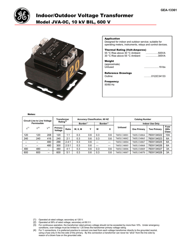
g GEA-13361 Indoor/Outdoor Voltage Transformer Model JVA-0C, 10 kV BIL, 600 V Application Designed for indoor and outdoor service; suitable for operating meters, instruments, relays and control devices. Thermal Rating (Volt-Amperes) 55 °C Rise above 30 °C Ambient ……………500VA 30 °C Rise above 55 °C Ambient ……………300VA Weight (approximate) Unfused ………………19 lbs Reference Drawings Outline: ………0122C34133 Frequency 50/60 Hz Notes: Circuit Line to Line Voltage Permissible ∆(1) 120 240 --480 600 (1) (2) (3) (4) Y(2) Y(4) 120 240 --480 600 208 416 480 480 --- Transformer Rating(3) Accuracy Classification, 60 HZ Burden(1) Catalog Number Burden(2) Indoor Use Only Primary Voltage Ratio W, X, M Y W X 120 240 288 300 480 600 1:1 2:1 2.4:1 2.5:1 4:1 5:1 0.3 0.3 0.3 0.3 0.3 0.3 0.6 0.6 0.6 0.6 0.6 0.6 0.3 0.3 ----0.3 0.3 0.6 0.6 ----0.6 0.6 Unfused 760X134001 760X134002 760X134004 760X134005 760X134006 760X134007 One Primary Two Primary Fuse 600v Class 760X134064 760X134065 760X134067 760X134068 760X134069 760X134070 760X134022 760X134023 760X134025 760X134026 760X134027 760X134028 10A 6A 6A 6A 3A 3A Operated at rated voltage; secondary at 120 V. Operated at 58% of rated voltage; secondary at 69.3 V. For continuous operation, the transformer rated primary voltage should not be exceeded by more than 10%. Under emergency conditions, over-voltage must be limited to 1.25 times the transformer primary voltage rating. For Y connections, it is preferred practice to connect one lead from each voltage transformer directly to the grounded neutral, using a fuse only in the line side of the primary. By this connection a transformer can never be “alive” from the line side by reason of a blown fuse on the grounded side. ________________________________________________________________________________________ Construction and Insulation The core and coil are placed in a plastic shell made from GE Valox and encapsulated in a polyurethane. Nameplate The nameplate is laser engraved aluminum. It is mounted on the top of the transformer. Provision is made for attaching the user’s identifying tag. Core & Coil The primary and secondary coils are precision wound on an insulated spool. Once the coils are wound, a distributed gap, grain oriented silicone steel core is positioned through the center of and around the outside of this combined coil. Cover A transparent, plastic terminal cover is furnished over the primary and secondary terminals. This cover provides a safe means of observing the electrical connections without requiring its removal. Primary Terminals These compression terminals, identified as H1 and H2, are conveniently located on top of the transformer. They are fixed, tin plated, brass posts with holes to accommodate No. 6 to No. 14 wire sizes. The brass screws for securing wires to the posts are tin-plated. Maintenance These transformers require no maintenance, other than occasional cleaning. Data subject to change without notice Secondary Terminals These compression terminals, identified as X1 and X2, are conveniently located on top of the transformer. They are fixed, tin plated, brass posts with holes to accommodate No. 6 to No. 14 wire sizes. The brass screws for securing wires to the posts are tin-plated. To purchase or obtain more information about GE Instrument Transformer products, please call GE’s Charlotte Service Center at 1-800-431-7867. Product information is also available on our web site at http://www.GEIndustrial.com. Click on the Product Index button (right column), select Transformers and follow the menus to Product Information or a Solutions Advisor H1 H2 H1 H2 VOLTAGE TRANSFORMER CAT 760X134_ _ _ TYPE JVA-OC PRI. 480V, BIL 10KV, 50-60 HZ 500 VA AT 30°C AMB ACC CL @ 60 HZ 0.3 W, X, M 300 VA AT 55°C AMB SERIAL NUMBER _ _ _ _ _ _ _ _ _ _ _ 4:1 X1 CLEARWATER, FL U.S.A. X2 X1 X2 120 JVA-0C Dimensions g 130 Main Street Somersworth, NH 03878 REV 0 – 11/02 1907 Calumet Street Clearwater, FL 33765 GE Industrial Systems


