MULTILAYER CERAMIC CAPACITORS
advertisement

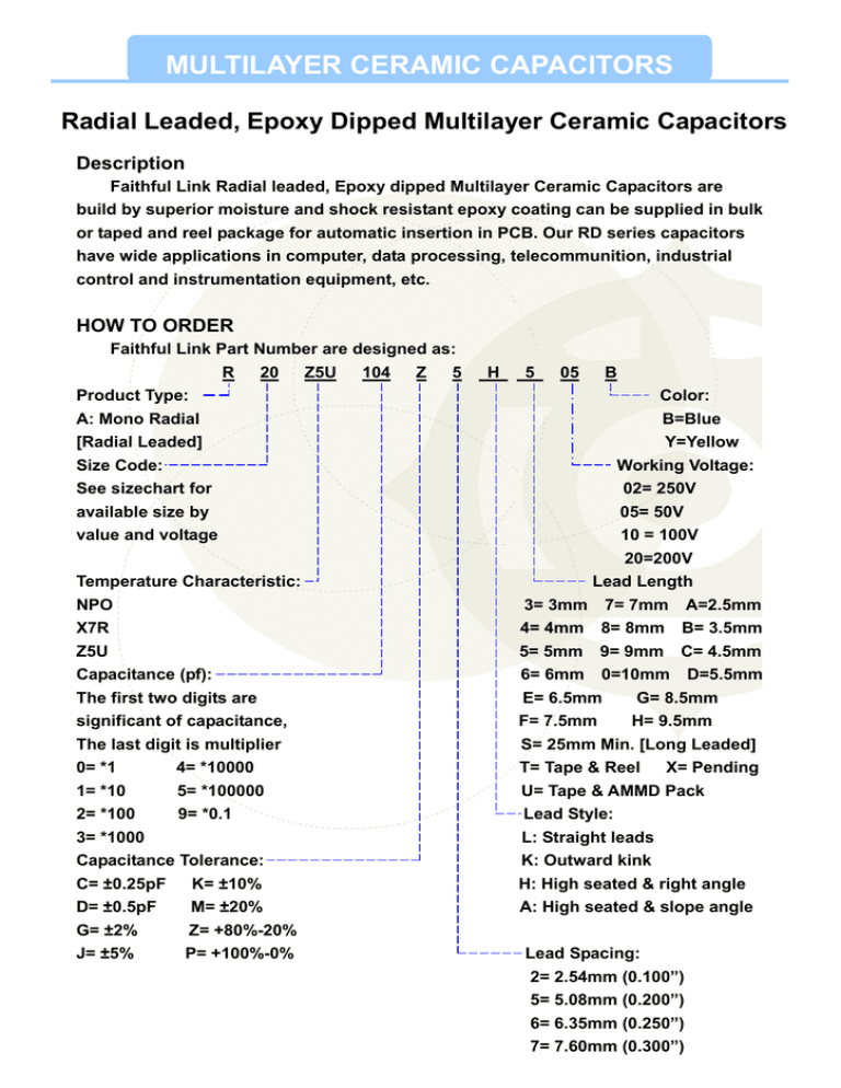
MULTILAYER CERAMIC CAPACITORS Radial Leaded, Epoxy Dipped Multilayer Ceramic Capacitors Description Faithful Link Radial leaded, Epoxy dipped Multilayer Ceramic Capacitors are build by superior moisture and shock resistant epoxy coating can be supplied in bulk or taped and reel package for automatic insertion in PCB. Our RD series capacitors have wide applications in computer, data processing, telecommunition, industrial control and instrumentation equipment, etc. HOW TO ORDER Faithful Link Part Number are designed as: R 20 Z5U 104 Z 5 Product Type: A: Mono Radial [Radial Leaded] Size Code: See sizechart for available size by value and voltage Temperature Characteristic: NPO X7R Z5U Capacitance (pf): The first two digits are significant of capacitance, The last digit is multiplier 0= *1 4= *10000 1= *10 5= *100000 2= *100 9= *0.1 3= *1000 Capacitance Tolerance: C= ±0.25pF K= ±10% D= ±0.5pF M= ±20% G= ±2% Z= +80%-20% J= ±5% P= +100%-0% H 5 05 B Color: B=Blue Y=Yellow Working Voltage: 02= 250V 05= 50V 10 = 100V 20=200V Lead Length 3= 3mm 7= 7mm A=2.5mm 4= 4mm 8= 8mm B= 3.5mm 5= 5mm 9= 9mm C= 4.5mm 6= 6mm 0=10mm D=5.5mm E= 6.5mm G= 8.5mm F= 7.5mm H= 9.5mm S= 25mm Min. [Long Leaded] T= Tape & Reel X= Pending U= Tape & AMMD Pack Lead Style: L: Straight leads K: Outward kink H: High seated & right angle A: High seated & slope angle Lead Spacing: 2= 2.54mm (0.100”) 5= 5.08mm (0.200”) 6= 6.35mm (0.250”) 7= 7.60mm (0.300”) MULTILAYER CERAMIC CAPACITORS Our Radial / Axial leaded, Epoxy dipped Multilayer Ceramic Capacitors are build by Superior moisture and shock resistant epoxy coating can be supplied in bulk or taped & reel package for automatic insertion in PCB. Our RD series capacitors have wide applications in computer, data processing, telecommunication, industrial control, and instrumentation equipment, etc. ■ Capacitance Range of Mono Radial ■ Capacitance Range of Mono Axial MULTILAYER CERAMIC CAPACITORS TYPICAL PERFOPMANCE CURVES MULTILAYER CERAMIC CAPACITORS SIZE CODE and DIMENSIONS: Units in inches (millimeter) Size CODE L W T R15 0.150 (3.81) 0.150 (3.81) 0.100 (2.54) R20 R30 0.200 (5.08) 0.300 (7.62) 0.200 (5.08) 0.300 (7.62) Lead Diameter Lead Length (G) (L) 0.2 (0.5) 0.150 (3.81) Lead Style 0.1 (2.54) L 0.2 (5.08) H.K.A 1.0 (25.0) 0.3 (7.62) H. 0.1 (2.5) 0.1 (2.54) L.K 0.2 (5.08) H.K 0.25 (6.35) H 0.3 (7.62) H 0.1 (2.5) 0.2 (5.08) H 1.0 (25) 0.3 (7.62) H 0.1 (2.5) 0.20 (2.54) 0.125 (3.18) Lead Spacing (S) 1.0 (25.0) 0.2 (0.5) Marking First line marked the Capacitance Value. Second line marked the TOL. WVDC, & T.C TDL: J= ±5%, K= ±10%, M= ±20%, Z= +80/-20% WVDC: 2= 25V, 5= 50V, A=100V, B= 200V T.C.: N= NPO, X= X7R, Z= Z5U Color Size Code 105 Capacitance ˇ Tolerance — Rated Voltage — Temp. Char. — Yellow R15 ˇ — — — Yellow R20, R30 ˇ ˇ ˇ ˇ Blue R15, R20, R30 MULTILAYER CERAMIC CAPACITORS Radial Tape & Reel Faithful Link has developed a tape and reel system of radially leaded components, which is suitable for the auto insertion machine. Dimension: Units in inches (millimeter) Description Symbol Body A Dimensions 0.4x0.4 [10.16x10.16] Description Feed hole pitch Maximum Wire lead diameter d (Mono-Kap) Feed Hole Diameter D +0.06 F .20±0.30 [5.08±0.76] .250±.040 [6.35±1.02] Overall tape thickness t .035 [0.89] Maximum Body thickness T .157 [3.99] Maximum Lead crimp height H0 .10±0.30 [2.54±0.76) Body inclination △h 0±0.4 [0 ±1.02] Top height H1 Rejected component Carrier tape width .630±0.02 to .710±.020 [16.0±.051 to 18.0±.051] W .710±.020[18.03±0.51] 1.27 [32.25] Maximum Adhesive tape width W0 .510 [12.95] Reference L .433 [11.00] Maximum Feed hole height off alignment W1 .350 −.020 [8.89 −0.51 ] P .500 ±0.39 [12.7±0.99] Adhesive tape margin W2 .120 [3.05] Reference out height Taping pitch lative pitch over two units. P2 0.157±0.012 (4±0.3) +0 ±.040 [±1.02] Accumu. .150±.020 [3.81±0.51] Feed hole off alignment 0 −. 120[ −3.05 ] P0 Dimensions P1 .020 −.0020 [0.51 −0.05 ] +0 Lead end protrusions Lead spacing +.0024 Symbol +0 PACKAGING QUANTITY Size Code R15 R20 R30 Taping Type Quantity per reel Quantity per box 2,500 2,000 2,500 2,000 2,500 2,000 Bulk Type Quantity per bag 1,000 1,000 1,000 +0 MULTILAYER CERAMIC CAPACITORS Axial Leaded, Epoxy Coated Multilayer Ceramic Capacitors Description Faithful Link Axial leaded, Epoxy Coated Multilayer Ceramic Capacitors are build by superior moisture and shock resistant epoxy coating. These capacitors are supplied in both bulk or taping and reel package for automatic insertion and sequencing with any axial leaded components. HOW TO ORDER Faithful Link Part Number are designed as: A 15 Z5U 104 Z A Product Type: A: Mono Axial Size Code: See sizechart for available size by value and voltage Temperature Characteristic: NPO X7R Z5U Y5V Capacitance (pf): The first two digits are significant of capacitance, The last digit is multiplier 0= *1 4= *10000 1= *10 5= *100000 2= *100 9= *0.1 3= *1000 Capacitance Tolerance: C= ±0.25pF K= ±10% D= ±0.5pF M= ±20% G= ±2% Z= +80%-20% J= ±5% P= +100%-0% A T 05 A Taping width: A= 52 mm [Standard] S= 26 mm X= Forming style Working Voltage 02 = 25V 05= 50V 10= 100V 20= 200V Lead Length 4= 4mm 8= 8mm 5= 5mm 9= 9mm 7= 7mm 0= 10mm C= 4.5mm F= 7.5mm D= 5.5mm G= 8.5mm E= 6.5mm H= 9.5mm T= Tape & Reel U= Tape & AMMD Pack Lead Styles A: Axial style [Standard] B: Forming style Lead Spacing A: Axial style [Standard] 5= 5.08mm (0.200”) 6= 6.35mm (0.250”) 7= 7.60mm (0.300”) 8= 8.89mm (0.350”) MULTILAYER CERAMIC CAPACITORS CAPACITANCE RANGE OF MONO AXIAL MULTILAYER CERAMIC CAPACITORS SIZE CODE and DIMENSIONS: Units in inches (millimeter) SIZE CODE L D LEAD DIA LEAD LENGTH A15 .150 [3.81] Max. .100 [2.54] Max. .020 [0.50] 1.00 [25.4] A20 .200 [5.08] Max. .125 [3.81] Max. .020 [0.50] 1.00 [25.4] AXIAL FORMING TYPE: Our axial-leaded capacitors can be supplied in forming type, which can only be in bulk package. 1,000 pcs per bag. LEAD SPACING 5= 0.200” [5.08mm] 6= 0.250” [6.36mm] LEAD LENGTH 4= 0.157” [4.0mm] 5= 0.197” [5.0mm] 6= 0.236” [6.0mm] 7= 0.276” [7.0mm] 8= 0.315” [8.0mm] 9= 0.354” [9.0mm] The dimensions are illustrated as the Following: TOL: +/- 0.031” [0.79mm] 7= 0.300” [7.62mm] 8= 0.350” [8.90mm] TOL: +/- 0.031” [0.79mm] 0= 0.394” [10.0mm] C= 0.177” [4.50mm] D= 0.217” [5.50mm] E= 0.256” [6.50mm] F= 0.295” [7.50mm] G= 0.335” [8.50mm] MARKING First line marked the Capacitance value. Second line marked the TOL, WVDC, & T.C. TOL: J=±5%, K=±10%, M=±20%, Z=+80/-20% 104 WVDC: 2=25V, 5=50V, A=100V, B=200V T.C.: N=NPO, X=X7R, Z=Z5U、Y5V SIZE CODE A15 Capacitance ˇ Tolerance ─ Rated Voltage ─ Temp. Char. ─ A20 ˇ ˇ ˇ ˇ MULTILAYER CERAMIC CAPACITORS AXIAL TAPE & REEL: Our axial-leaded capacitors can be supplied taped and reeled. A 12 inch leader of tape starts and ends each reel. A layer of 50/60 lb. Kraft paper separates each layer of components, and a layer of corrugated cardboard over the last layer protects the contents of the reel. Reels are to EIA standards (RS-296E Class, I, Level I). Dimension: Units in inches (millimeter) Description Pitch of Component Symbol Dimensions P .200±.020 [5.08±0.51] Cumulative Tolerance of P over 6 consecutive units Description Symbol Dimensions C ±.030 [±0.76] ±.0059 [±0.15] Core diameter D1 1.375-3.260 [34.90-92.10) Centered Tape width Wt .236±.039 [6±1.0] Reel Diameter D2 14 MAX. (355.60) Lead Wire Protrusion Le .062 Max. [1.57] Core Width W1 2.750±0.060 [69.85±1.52) Lead Extension into Tape Li .156 Min. [3.96] Recess Depth R .374 MIN. [9.5) .031 Max. [0.8] Arbor Hole Ho .510-.608 [15.5-18.0] △h .047 MAX. [1.19] L 12 MIN. [304.8] Offset Between Tapes △T Width Between Tapes W 2.06±.062 [52.37±1.57] Pilot Hole DIA H1 .315 [8.0] Deflection from Nominal position Leader option PACKAGING QUANTITY Taping Type SIZE CODE Bulk Type Quantity per reel Quantity per box Quantity per bag A15 10,000 5,000 1,000 A20 10,000 5,000 1,000


