Power Factor Correction Whitepaper
advertisement
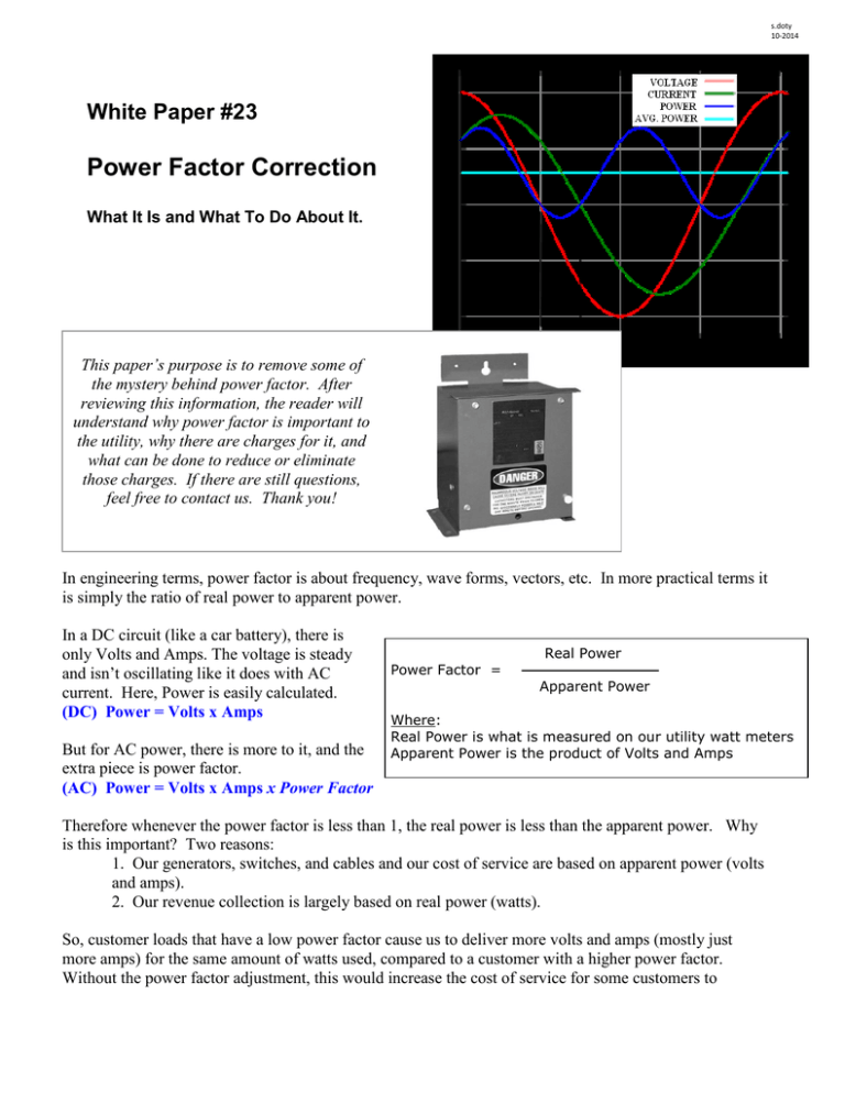
s.doty 10-2014 White Paper #23 Power Factor Correction What It Is and What To Do About It. This paper’s purpose is to remove some of the mystery behind power factor. After reviewing this information, the reader will understand why power factor is important to the utility, why there are charges for it, and what can be done to reduce or eliminate those charges. If there are still questions, feel free to contact us. Thank you! In engineering terms, power factor is about frequency, wave forms, vectors, etc. In more practical terms it is simply the ratio of real power to apparent power. In a DC circuit (like a car battery), there is only Volts and Amps. The voltage is steady and isn’t oscillating like it does with AC current. Here, Power is easily calculated. (DC) Power = Volts x Amps But for AC power, there is more to it, and the extra piece is power factor. (AC) Power = Volts x Amps x Power Factor Power Factor = Real Power Apparent Power Where: Real Power is what is measured on our utility watt meters Apparent Power is the product of Volts and Amps Therefore whenever the power factor is less than 1, the real power is less than the apparent power. Why is this important? Two reasons: 1. Our generators, switches, and cables and our cost of service are based on apparent power (volts and amps). 2. Our revenue collection is largely based on real power (watts). So, customer loads that have a low power factor cause us to deliver more volts and amps (mostly just more amps) for the same amount of watts used, compared to a customer with a higher power factor. Without the power factor adjustment, this would increase the cost of service for some customers to compensate for others. With the power factor charge, only those customers with low power factors pay the charge, and it is fair to all. Sometimes a visual aid helps with this concept. Consider a mug of root beer. The ‘mug’ represents the current carrying capacity of the generator or cable. When there is foam, there is less room for root beer; when there is low power factor there is less capacity for transmitting power. With less foam, the mug holds more root beer - more power can be transmitted without having to buy bigger cables. That’s why we like high power factors! We charge for the foam Root Beer True Power Apparent Power What causes low power factor? Understanding ‘why’ will lead to the answer of what to do about it. What drives low power factor is when the current and voltage are out of synch. See the wave form chart at the top of the paper. If “time” is proceeding to the right, you can see that the current wave is behind the voltage wave. In a perfect world they would occur simultaneously. When the current lags behind as shown, the power factor starts to droop – the more it lags the worse the power factor. What causes the lag is usually something in the building utilizing an electromagnetic principle to operate. The build-up of a magnetic field takes some time. In the case of DC this process occurs once, but in the case of alternating current it is forever building and collapsing the magnetic field……and that’s when current lags voltage. Common things that contribute to low power factor (think magnetic): Motors Older magnetic lighting ballast Solenoids and lifting magnets Welders Battery chargers, inverters, transformers and some power supplies Oversized equipment Some modern devices include on-board power factor correction, others do not. In the end, each customer’s facility is a mixture of different individual loads and power factors, stirred together and connected to the utility transformer. For customers large enough to be on a demand-based rate, we use meters to record the demand. These same meters record power factor. For residential and small commercial customers the power factors are more uniform and we use an assumed average value rather than expensive meters. How are power factor penalties billed? Our billing system collects revenue for low power factor by raising the demand charges. We correct our power factor leaving the generating station to 95% or higher, and any customer with a power factor of 0.95 (95%) or higher will not have a power factor charge. But, for each percent below 95% the demand charge is increased by an equal amount. For example, if the customer’s power factor is 85%, that is 10 percentage points below the 95% limit – thus the demand charge is increased by 10%. It’s not a separate line item, but knowing how the bill is calculated allows any customer to determine what their power factor charge is. This is described in more detail in White Paper #22 “Understanding Large Commercial Electric Bills.” How can power factor costs be reduced? By improving the power factor, the charges will be proportionally reduced; if the power factor is raised to 95% or higher consistently, there will be no power factor charges at all. How to improve facility power factor. Step 1. Determine how much is being spent on power factor. Step 2 Find the source of low power factor. Step 3. Correct the power factor. Step 1. This initial step does two things for the customer. A. It shows how much can be saved (maximum savings = the amount of power factor charges). This provides a sanity check for evaluating the cost of the corrective measures in Step 3. For example if the cost of correcting power factor is $10,000 it would probably make sense to do if the potential savings are $5,000 per year (2 year payback), but probably would not make sense if the potential savings are only $1,000 per year (10 year payback). This is a customer choice. B. It shows the consistency pattern of the low power factor. When the low power factor is consistently or seasonally low, the remedies are more straight forward than when power factor charges occur randomly throughout the year. Step 2. This step is best done with a persons specializing in power factor correction. The measurements taken will show where the power factor - offending equipment is plus other important measurements like “harmonics” (see Appendix). In some cases, for example, the power factor may come from one large unit. In others it may come from a group of motors in one room. In other cases the power factor issue comes from lots of smaller equipment spread around the building. www.bis.fm www.fluke.com Portable Power Factor Test Equipment It is interesting to note that the power factor of a piece of equipment is not a fixed value – it may be one value at full load or on a nameplate and another at reduced load. Oversized equipment that runs at a light load most of the time will make the power factor worse in most cases. For motors this has been well documented. Where practical, it is best to correct the power factor (raise it) at the device itself; e.g. at the motor. The reason for this is subtle but can be important. First, the power factor correction effect is only felt upstream of the correction equipment. Consider a large motor with an 80% power factor. With a PF correction capacitor at the motor, the extra current carried from low power factor is only ‘felt’ by the wiring between the correction equipment and the motor – a short distance. But if the correction capacitor is located at the main service entrance, all the building wiring between the two points still ‘feels’ the extra current. Power Factor Correction Capacitor Locations Second, correction equipment at a main service often needs the additional feature of variable correction to compensate for changing loads (different equipment running) – when installed at individual equipment the solution is often simplified since it is only in effect when that equipment is turned on. Each facility will have its own ‘best’ solution that balances performance with practicality and cost. Step 3. Get expert advice before choosing equipment to correct the power factor. www.syntron.co.in www.capacitorconvertors.com Fixed Capacitor Automatic Switching Adjustable Capacitor Unit In many cases, the power factor is low due to motor loads and can be easily corrected with properly sized fixed capacitors. In some cases variable loads are met with variable capacitor equipment that continuously adjusts the capacitance to keep the power factor high. And then there are loads sensitive to harmonics; these bear special consideration. Since each customer site is unique, a one-size-fits-all approach doesn’t work. While capacitors won’t create harmonic issues, harmonics can create issues for capacitors. The presence of high amounts of harmonics can cause significantly reduced life span of a capacitor which spoils the planned economic return for the project. The reasons for this lie in engineering analysis, but the bottom line is that if the customer facility has a lot of harmonics in it, the chances are it will not be compatible with fixed capacitor solutions. For such buildings there are special electronic “power conditioning“ units available that eliminate or filter the harmonics to assure the compatibility. Facilities with significant amounts of high tech equipment like switching power supplies, computer controlled robotics, are red flags for harmonics concern. To be certain, the survey (Step 2) would include harmonic measurements as well as power factor measurements. If harmonics are found to be significant, power factor correction will usually require a different approach. Special electronic power conditioning solutions are available, such as Static Var Compensators. These high speed electronic controllers monitor the voltage/current waves and inject canceling waves to smooth it all out. Another proven technology is a synchronous motor – by the nature of this special motor it serves to adjust power factor - the motor turns but isn’t connected to anything mechanically. www.squared.com www.pscpower.com Electronic Power Conditioning with Power Factor Correction Synchronous Motor PF Correction APPENDIX: Harmonics Harmonics are becoming more and more common with technology advances, so a basic understanding of what it is and what to watch out for are good tools to have. An electrical engineer could spend hours discussing this subject because it is very complex. This paper will limit the discussion to why it can be of concern in a building. Harmonics are resonant frequencies. Usually they operate at higher frequencies than standard 60 cycle line current, but one thing all harmonic frequencies have in common is that they have wave forms that match the 60 cycle utility supply at some point and do so repeatedly. This has the effect of adding to the wave’s size and distorting it. www.hersheyenergy.com www.cpe-aim.ca For example a wave operating at 120 Hz would align with the 60 cycle wave form every other peak. This is called the first harmonic. As it happens, the most troublesome harmonics are the 5th to 7th but all harmonics are a potential source of trouble. These rogue waves superimposed on top of the utility wave shape create “harmonic distortion” because it changes the wave’s shape. Too much distortion creates issues with sensitive electronic equipment; the ‘noise’ (irregularities in the wave form” can confuse some equipment. For this reason, facilities like data centers will often use special power conditioning equipment to clean up the waves to a clean sine wave. In the case of power factor correcting capacitors, a different issue exists with harmonics, having to do with the frequency. Due to the nature of capacitors, the harmonic component on the lines “looks like” a short circuit and pass through the capacitor; this effect is more pronounced at higher frequencies. If sufficient quantity of this harmonic current exists the capacitor will be stressed, overheat and fail prematurely – as in a year’s time or less. Other harmonic-related issues include nuisance tripping of circuit breakers and heating of neutral conductors. It’s all bad. IEE-519 is a standard that prescribes the maximum amount of harmonics a customer should generate to avoid issues with utility services (we don’t want it either) or your neighbors. Of course all of it goes away if there are no harmonics in the first place. But some equipment vital to business operation inherently creates harmonics, so what to do? Consider typical equipment that is notorious for creating harmonics: Switch Mode Power Supplies Variable Frequency Drives (VFDs) Where possible, specifying this equipment with on-board filters or inherent designs that limit harmonic generation will pay dividends by making the whole problem smaller. Using our example certain power supplies or certain VFDs emit fewer harmonic, or accessories can be provided to snub them at the source. As a second tier action item, isolating large harmonic creation equipment with filters or isolation transformers can restrict it to just that area. The other approach is to invest in building power conditioning equipment to actively neutralize it. Usually the business operations personnel are aware of the phenomena when harmonics are prevalent in their industry, and the consulting engineers that design the buildings and infrastructure to support the business are trained to deal with it. Suppliers of power factor correction equipment are also good sources of knowledge on harmonics. Seeking the advice of such experts is a good place to start.


