Lec 12 WFig ver 01
advertisement

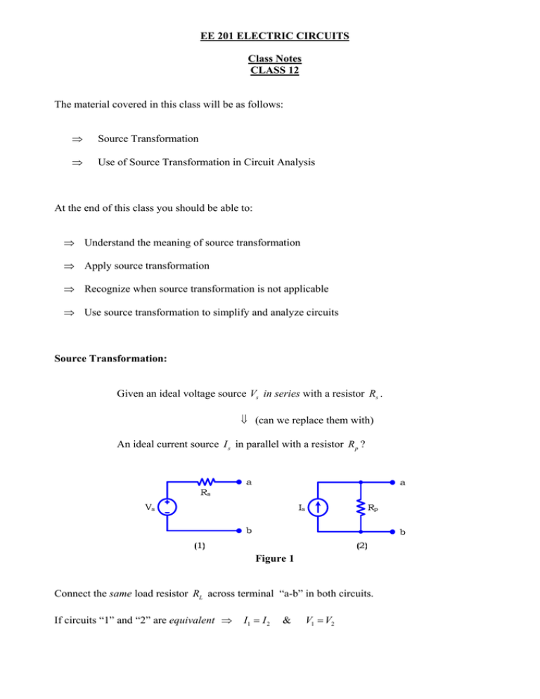
EE 201 ELECTRIC CIRCUITS Class Notes CLASS 12 The material covered in this class will be as follows: ⇒ Source Transformation ⇒ Use of Source Transformation in Circuit Analysis At the end of this class you should be able to: ⇒ Understand the meaning of source transformation ⇒ Apply source transformation ⇒ Recognize when source transformation is not applicable ⇒ Use source transformation to simplify and analyze circuits Source Transformation: Given an ideal voltage source Vs in series with a resistor Rs . ⇓ (can we replace them with) An ideal current source I s in parallel with a resistor R p ? Figure 1 Connect the same load resistor RL across terminal “a-b” in both circuits. If circuits “1” and “2” are equivalent ⇒ I1 = I 2 & V1 = V2 Circuit “1” ⇒ I1 = Circuit “2” ⇒ I1 = I 2 ⇒ Vs Vs = Req Rs + RL I2 = Rp R p + RL Is Rp I s Vs = Rs + RL R p + RL (1) (2) (CDR is used) (3) If we choose R p = Rs ⇒ Vs = I s R p = I s Rs ∴ Rs = R p & Vs = I s Rs ⇓ ⇔ Vs in series with Rs I s in parallel with Rs Figure 2 The above conversion is called Source Transformation (ST). Circuits (1) & (2) are equivalent. However, they are not the same. When any load is connected to terminals “ a ” & “ b ” of circuits (1) & (2) ⇓ Load cannot distinguish between the two circuits. Circuits (1) & (2) are equivalent from the outside when accessed from terminals “a” & “b”. Circuits (1) & (2) are different from the inside. Example 1: Covert the following circuits using ST. Figure 3 Solution: Circuit (1): R p = Rs = 2Ω Is = Vs 3 = = 1.5 A Rs 2 ≡ Figure 4 Circuit (2): R p = Rs = 5Ω Is = Vs 4 = = 0.8 A (downwards. Why?) Rs 5 ≡ Figure 5 Example 2: Covert the following circuits using ST. Figure 6 Solution: Circuit (1): Rs = R p = 3Ω Vs = Rs I s = 3(3) = 9V & ≡ Figure 7 Circuit (2): Rs = R p = 5Ω & Vs = Rs I s = 5(2) = 10V (upper voltage polarity is negative. Why?) ≡ Figure 8 You need to be careful when using ST, as we will see in the next example. Example 3: Covert the following circuits using ST. Figure 9 Solution: Circuit (1): A resistor in parallel with a voltage source (not in series) ⇒ ST does not apply. A resistor in parallel with a voltage source ⇒ equivalent to a voltage source. a 3V 2 ≡ a 3V b b Figure 10 Circuit (2): A resistor in series with a current source (not in parallel) ⇒ ST does not apply. ≡ Figure 11 A resistor in series with a current source ⇒ equivalent to a current source. Example 4: Use ST to calculate: a) i1 b) i2 Figure 12 Solution: It is a good idea to first label some points on the circuit. Figure 13 Apply ST to the 2 A & 1Ω combination ⇒ V = IR = 2(1) = 2V Notice that i2 cannot be drawn. It disappears. Why? The current through the 1Ω of the transformed circuit is not i2 . Why? Reason: R p = Rs means the two resistors have the same value. It does not mean we have the same resistor!! Q 2Ω & 1Ω in series ⇒ current through the 1Ω of the transformed circuit is i1 . Figure 14 2Ω & 1Ω in series 8V ⇒ & 2V in series ⇒ a) i1 = 3Ω 8 − 2 = 6V 6 = 2A 3 b) KCL at node “ a ” (of the original circuit) ⇒ i2 = i1 + 2 = 2 + 2 = 4 A Figure 15 Figure 12 Example 5: Use ST to calculate V . Figure 16 Solution: Apply ST to ( 3V in series with 1Ω ) & ( 18V in series with 2Ω ) I s1 = 3 = 3A 1 & Is2 = 18 = 9A 2 Figure 17 1Ω 3Ω 2Ω 3A 9 A ⇒ ⇒ Req = 1 = 0.545Ω 1 1 1+ + 3 2 I eq = 9 − 3 = 6 A ∴V = I eq Req = 6(.545) = 3.273V Figure 18 Example 5: Using ST, calculate: a) i1 b) i2 Figure 19 Solution: ST ⇒ V = 3 × 2 = 6V Figure 20 2Ω 8Ω 10Ω ⇒ Figure 21 ST ⇒ I= 6 = 0.6 A 10 Figure 22 1Ω 10Ω ⇒ 10 × 1 10 = = 0.909Ω 10 + 1 11 Figure 23 ST ⇒ V = 0.909 × 0.6 = 0.545V Figure 24 Req = 5 + 0.909 = 5.909Ω a) ∴ i1 = & Veq = 7 + 0.545 = 7.545V 7.545 = 1.277 A 5.909 b) KVL (in the original circuit) ⇒ −7 + 5i1 + 1i2 = 0 ⇒ −7 + 5(1.277) + 1i2 = 0 ⇒ i2 = 0.615 A Figure 25 Figure 19


