SP-3100 Instruction Sheet

SP-3100 INDOOR ALARM
The BBLA alarm system is designed to monitor liquid levels in sump basins, holding tanks, lift stations tanks and many other non-potable water and wastewater applications.
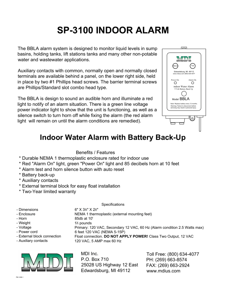
Auxiliary contacts with common, normally open and normally closed terminals are available behind a panel, on the lower right side, held in place by two #1 Phillips head screws. The barrier terminal screws are Phillips/Standard slot combo head type.
The BBLA is design to sound an audible horn and illuminate a red light to notify of an alarm situation. There is a green line voltage power indicator light to show that the unit is functioning, as well as a silence switch to turn horn off while fixing the alarm (the red alarm light will remain on until the alarm conditions are remedied).
Silence Test
Edwardsburg, MI. 49112 www.mdius.com (800) 634-4077
Power On Alarm On
I ndoor Water Alarm
9 Volt Battery Back Up
Model
BBLA
Note: Replace battery every 12 months.
Warning: Failure to disconnect before servicing may result in personal injury.
Indoor Water Alarm with Battery Back-Up
Benefits / Features
* Durable NEMA 1 thermoplastic enclosure rated for indoor use
* Red "Alarm On" light, green "Power On" light and 85 decibels horn at 10 feet
* Alarm test and horn silence button with auto reset
* Battery back-up
* Auxiliary contacts
* External terminal block for easy float installation
* Two-Year limited warranty
- Dimensions
- Enclosure
- Horn
- Weight
- Voltage
- Power cord
- External block connection
- Auxiliary contacts
Specifications
6" X 3 3
4
" X 2 1
2
"
NEMA 1 thermoplastic (external mounting feet)
85db at 10'
1 1
3
pounds
Primary: 120 VAC, Secondary 12 VAC, 60 Hz (Alarm condition 2.5 Watts max)
6 feet 120 VAC (NEMA 5-15P)
Float connection. DO NOT APPLY POWER!
Class Two Output, 12 VAC
120 VAC, 5 AMP max 60 Hz
MDI Inc.
P.O. Box 710
25028 US Highway 12 East
Edwardsburg, MI 49112
Toll Free: (800) 634-4077
PH: (269) 663-8574
FAX: (269) 663-2924 www.mdius.com
PM-1498-1
INDOOR ALARM SYSTEM
INSTALLATION INSTRUCTIONS
Be sure to follow National Electric Code, ANSI/NFPA 70, when installing this unit to prevent moisture from entering or building up inside equipment.
ALARM & FLOAT INSTALLATION
ALARM
1.
Install 9V battery (not included). Replace battery once a year.
2.
Select an indoor mounting location.
3.
Install a mounting screw in the wall at the desired height and slip keyhole on the back of the box onto the screw and pull down.
4.
Use another screw to fasten bottom mounting cleat to the wall.
5.
Use cable tie supplied in the box to secure the float switch at the desired warning level in the tank (see diagram). Cut off excess material left from cable tie and discard.
6.
Now manually test the alarm by tilting the float switch up until you hear the alarm notification and you see the alarm light turn on.
7.
Periodically test unit by pushing the test button on the cover to make sure the unit is working properly.
ALARM
SWITCH
HIGH LEVEL APPLICATION SHOWN HERE
WARNING: FAILURE TO FOLLOW INSTRUCTIONS MAY RESULT IN SERIOUS
PERSONAL INJURY OR DEATH. REFER TO THESE INSTRUCTIONS ANY TIME
THE UNIT IN DISCONNECTED FOR ANY REASON
WARNING ELECTRICAL SHOCK HAZARD
DISCONNECT POWER BEFORE INSTALLING OR
SERVICING THIS PRODUCT, A QUALIFIED SERVICE
PERSON MUST INSTALL AND SERVICE THIS
PRODUCT. ACCORDING TO APPLICABLE
ELECTRICAL & PLUMBING CODES.
WARNING
E
EXPLOSION OR FIRE HAZARD
DO NOT USE THIS PRODUCT WITH FLAMMABLE
LIQUIDS. DO NOT INSTALL IN HAZARDOUS
LOCATIONS AS DEFINED BY NATIONAL ELECTRIC
CODE, ANSI/NFPA 70.

