Datasheet - Future Electronics
advertisement

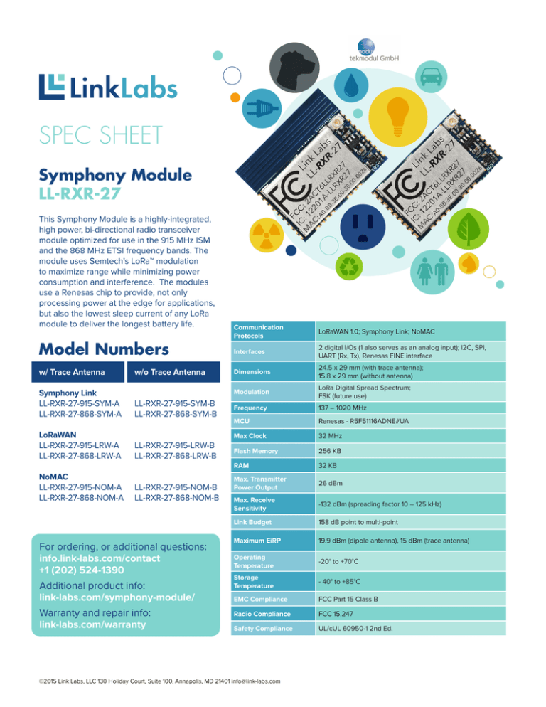
SPEC SHEET Symphony Module LL-RXR-27 This Symphony Module is a highly-integrated, high power, bi-directional radio transceiver module optimized for use in the 915 MHz ISM and the 868 MHz ETSI frequency bands. The module uses Semtech’s LoRa™ modulation to maximize range while minimizing power consumption and interference. The modules use a Renesas chip to provide, not only processing power at the edge for applications, but also the lowest sleep current of any LoRa module to deliver the longest battery life. Model Numbers w/ Trace Antenna w/o Trace Antenna Symphony Link LL-RXR-27-915-SYM-A LL-RXR-27-868-SYM-A LL-RXR-27-915-SYM-B LL-RXR-27-868-SYM-B LoRaWAN LL-RXR-27-915-LRW-A LL-RXR-27-868-LRW-A LL-RXR-27-915-LRW-B LL-RXR-27-868-LRW-B NoMAC LL-RXR-27-915-NOM-A LL-RXR-27-868-NOM-A LL-RXR-27-915-NOM-B LL-RXR-27-868-NOM-B For ordering, or additional questions: info.link-labs.com/contact +1 (202) 524-1390 Additional product info: link-labs.com/symphony-module/ Warranty and repair info: link-labs.com/warranty Communication Protocols LoRaWAN 1.0; Symphony Link; NoMAC Interfaces 2 digital I/Os (1 also serves as an analog input); I2C, SPI, UART (Rx, Tx), Renesas FINE interface Dimensions 24.5 x 29 mm (with trace antenna); 15.8 x 29 mm (without antenna) Modulation LoRa Digital Spread Spectrum; FSK (future use) Frequency 137 – 1020 MHz MCU Renesas - R5F51116ADNE#UA Max Clock 32 MHz Flash Memory 256 KB RAM 32 KB Max. Transmitter Power Output 26 dBm Max. Receive Sensitivity -132 dBm (spreading factor 10 – 125 kHz) Link Budget 158 dB point to multi-point Maximum EiRP 19.9 dBm (dipole antenna), 15 dBm (trace antenna) Operating Temperature -20° to +70°C Storage Temperature - 40° to +85°C EMC Compliance FCC Part 15 Class B Radio Compliance FCC 15.247 Safety Compliance UL/cUL 60950-1 2nd Ed. ©2015 Link Labs, LLC 130 Holiday Court, Suite 100, Annapolis, MD 21401 info@link-labs.com 24.5mm 8.7mm 1 2 3 4 5 6 7 8 9 9.75mm RXR3 PINOUT 10 5.75mm 12 13 14 15 16 4.75mm Notes: 1. RF connection is via U.FL connector on upper left side of the module or Pin 2 2. RF output is 50 Ω, DC blocking capacitor not required 3. ALL I/O signals must be 3.3 V. If necessary, pin 4 (3.3 OUT) may be used to supply an offmodule level shifter 4. Default UART baud rate is 115,200 8n1 5. If possible, keep area under module free of copper. If not possible, ensure all features are masked. 6. If using VBAT, you must tie LDO_OUT to VCC 11 ANTENNA 29mm Symphony Module LL-RXR-27 25 24 23 22 21 20 19 1.75mm 18 17 All pads are 1.5mm square Pin # Name Type Description Pin # Name Type Description 2 ANT 1,2 RF I/O RF path if not using U.FL connector 13 SMOSI1/ SSDA16 IO SPI1: master out slave in 3 VBAT Input Voltage Optional unregulated supply voltage 3.5 to 5.5V 15 SCK16 IO SPI1: serial clock 4 LDO_OUT5 Output Voltage Power digital. 3.3V 5 VCC Input Voltage 6 MD/FINED 7 17 BOOT I NC = Boot normally, GND = Bootloader Regulated supply voltage. 2.5 - 3.3V 18 nSS16 IO SPI1: slave select 19 FINEC IO FINE interface IO FINE interface nRESET I External reset pin, active low 8 HOST_IO0 O 10 SDA06 11 12 22 6 Analog Input I 0 – VCC 23 HOST_RXIN4 I UART interface: module Rx Status message indicator 24 HOST_ TXOUT4 O UART interface: module Tx IO I2C0: serial data SCL06 IO I2C0: serial clock 1, 9, 25 GND Ground – SMISO1/ SSCL16 IO SPI1: master in slave out 14, 16, 20, 21 Reserved – – For ordering, or additional questions: info.link-labs.com/contact +1 (202) 524-1390 Additional product info: link-labs.com/symphony-module/ Warranty and repair info: link-labs.com/warranty ©2015 Link Labs, LLC 130 Holiday Court, Suite 100, Annapolis, MD 21401 info@link-labs.com


