Quick Connect Cable Specifications
advertisement
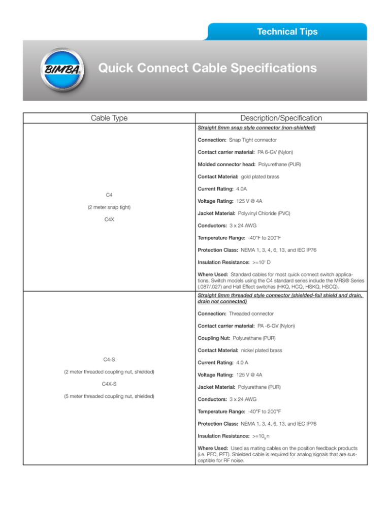
Technical Tips Quick Connect Cable Specifications Cable Type Description/Specification Straight 8mm snap style connector (non-shielded) Connection: Snap Tight connector Contact carrier material: PA 6-GV (Nylon) Molded connector head: Polyurethane (PUR) Contact Material: gold plated brass Current Rating: 4.0A C4 Voltage Rating: 125 V @ 4A (2 meter snap tight) Jacket Material: Polyvinyl Chloride (PVC) C4X Conductors: 3 x 24 AWG Temperature Range: -40°F to 200°F Protection Class: NEMA 1, 3, 4, 6, 13, and IEC IP76 Insulation Resistance: >=10' D Where Used: Standard cables for most quick connect switch applications. Switch models using the C4 standard series include the MRS® Series (.087/.027) and Hall Effect switches (HKQ, HCQ, HSKQ, HSCQ). Straight 8mm threaded style connector (shielded-foil shield and drain, drain not connected) Connection: Threaded connector Contact carrier material: PA -6-GV (Nylon) Coupling Nut: Polyurethane (PUR) Contact Material: nickel plated brass C4-S (2 meter threaded coupling nut, shielded) C4X-S (5 meter threaded coupling nut, shielded) Current Rating: 4.0 A Voltage Rating: 125 V @ 4A Jacket Material: Polyurethane (PUR) Conductors: 3 x 24 AWG Temperature Range: -40°F to 200°F Protection Class: NEMA 1, 3, 4, 6, 13, and IEC IP76 Insulation Resistance: >=109 n Where Used: Used as mating cables on the position feedback products (i.e. PFC, PFT). Shielded cable is required for analog signals that are susceptible for RF noise. Right angle 8mm threaded style connector (shielded-foil shield and drain, drain not connected) C5 or C5-S (2 meter right angle threaded coupling nut, shielded) Connection: Threaded connector Notes: • All quick connect products use a universal male connector that can use either a threaded or snap connector. • All accessory cables can be ordered separately. (i.e., for MRS® or Hall Effect quick connect switch applications where customers prefer a threaded coupling between the switch and the cable., or required shielded cable.) Wire Color Codes: Switch Wire Codes All switch wiring conforms to the CENELEC EN 50 044 wiring standard, which designates the following: Blue - (+) Positive Brown - Signal Output Black - Signal Output (to load) Important Note: 2 wire switches only use the Blue and Brown wires. Do not connect the Blue and Brown wires across the power supply, as the switch will short out. For Sinking Circuits, connect the Blue wire to ground (negative), and the Brown wire to the PLC Sinking Input. For Sourcing Circuits, connect the Brown wire to (+) Positive, and the Blue wire to the PLC Sourcing Input. Position Feedback Products Wire Codes Position Feedback Products do not conform to the CENELEC standard. The Position Feedback products use the following wire color code: Blue - (+) Positive Brown - Signal Output Black - (-) Negative The information presented is in Bimba’s best engineering opinion and should be used for reference only. Recommendations derived should be verified under actual operating conditions. Bimba reserves the right to change specifications without prior notice. Bimba Manufacturing Company Monee, IL 60449-0068 Telephone: 708.534.8544 Email: cs@bimba.com www.bimba.com Rev Level: 0 Leaders in Actuation. To learn more about this product, scan this QR code with your mobile device.
