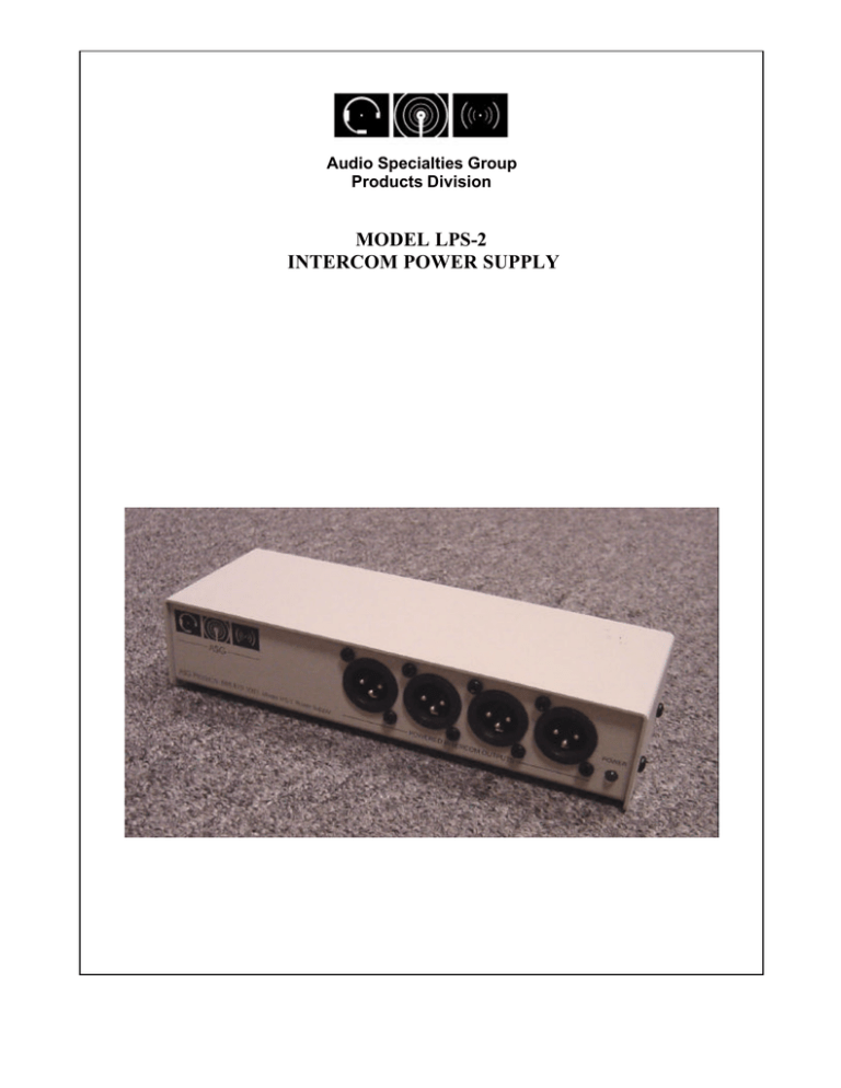
MODEL LPS-2 INTERCOM POWER SUPPLY
advertisement

Audio Specialties Group Products Division MODEL LPS-2 INTERCOM POWER SUPPLY Audio Specialties Group Products Division LPS-2 1.0 Introduction The LPS-2 intercom power supply serves both as the source of power and the common audio signal termination for portable and fixed location user stations. The LPS-2 is designed to work with Clear-Com and RTS type intercom equipment, though when using RTS equipment, only channel #2 will be usable. 2.0 Internal Settings When the LPS-2 is used in conjunction with the ASG AOB-2 audio interface adapter, the termination is derived from the host intercom equipment. Since the LPS-2 is typically used this way, the internal termination is factory set to the “OFF” position using JP1 on the circuit board inside the chassis. If a beltpack is connected to the supply without the termination turned on OR the balanced audio connection is not tied to a host system, there will be excessive audio level in the earpiece. To fix this condition, set he internal jumper to terminate, or connect the LPS-2 to a host system set for 200 ohms. 3.0 Capabilities Due to the use of high performance power designs, including a high efficiency torodial power transformer, the LPS-2 can supply sufficient current to power up to eight beltpacks with 50 ohm ear-pieces or four speaker stations with 8-ohm speakers. The four XLR powered outputs can each connect to a single station or one output could be wired in “daisy-chain” style to all the stations. The green POWER LED indicates power after the regulation circuitry. If a short circuit in the station wiring occurs, the LED will extinguish indicating a problem in the wiring. The internal circuitry provides for thermal and short circuit protection. Additionally, there is a fuseable resistor in series with the output of the regulator to add protection to the circuit board should any voltage be connected to the outputs of the supply. 4.0 Connecting to other Systems The balanced audio connection is DC protected to 50V and is transformer isolated from the rest of the circuitry. Ferrite beads on the input provide additional immunity to noise and RF interference. The input level can be up to +7dBv with less than .1% distortion. The binding posts, RJ-11 and the female XLR connector are in parallel. The polarity of the incoming signal is not significant to the performance or proper use of the device. 2 Electrical Specifications Dimensions (Specifications at 120V AC line voltage) Height: 1.71” Width: 8.1” Balanced Audio In/Out Depth: 2.75” Nominal operating level: -2dBv Weight: 2LBS Maximum AC signal <1% THD+N: +7dBv Maximum DC signal (peak or sustained): 50V Power Outputs Nominal DC voltage across pins 1 and 2: 23.1V AC impedance across pins 1 and 2: .5 ohm AC impedance across pins 1 and 3 Internal termination set to ON: 200 ohm Internal termination set to OFF: on host system termination value dependant Maximum current @ 23V DC: 450mA Power requirements 120V AC 60Hz 22W AC Mains fuse GMA 1A (internal) Environmental Temperature Operating: 32O to 110O F Do not expose unit to rain. 3


