Dynamic phasors in modeling and analysis of unbalanced
advertisement
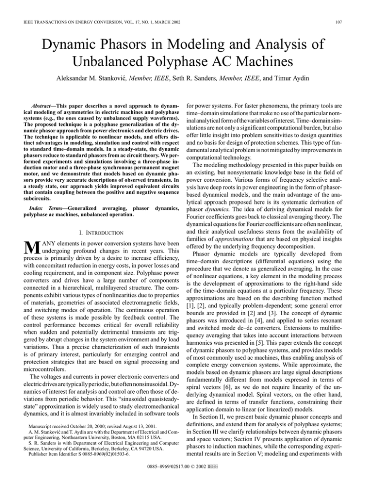
IEEE TRANSACTIONS ON ENERGY CONVERSION, VOL. 17, NO. 1, MARCH 2002 107 Dynamic Phasors in Modeling and Analysis of Unbalanced Polyphase AC Machines Aleksandar M. Stanković, Member, IEEE, Seth R. Sanders, Member, IEEE, and Timur Aydin Abstract—This paper describes a novel approach to dynamical modeling of asymmetries in electric machines and polyphase systems (e.g., the ones caused by unbalanced supply waveforms). The proposed technique is a polyphase generalization of the dynamic phasor approach from power electronics and electric drives. The technique is applicable to nonlinear models, and offers distinct advantages in modeling, simulation and control with respect to standard time–domain models. In a steady-state, the dynamic phasors reduce to standard phasors from ac circuit theory. We performed experiments and simulations involving a three-phase induction motor and a three-phase synchronous permanent magnet motor, and we demonstrate that models based on dynamic phasors provide very accurate descriptions of observed transients. In a steady state, our approach yields improved equivalent circuits that contain coupling between the positive and negative sequence subcircuits. Index Terms—Generalized averaging, phasor polyphase ac machines, unbalanced operation. dynamics, I. INTRODUCTION M ANY elements in power conversion systems have been undergoing profound changes in recent years. This process is primarily driven by a desire to increase efficiency, with concomitant reduction in energy costs, in power losses and cooling requirement, and in component size. Polyphase power converters and drives have a large number of components connected in a hierarchical, multilayered structure. The components exhibit various types of nonlinearities due to properties of materials, geometries of associated electromagnetic fields, and switching modes of operation. The continuous operation of these systems is made possible by feedback control. The control performance becomes critical for overall reliability when sudden and potentially detrimental transients are triggered by abrupt changes in the system environment and by load variations. Thus a precise characterization of such transients is of primary interest, particularly for emerging control and protection strategies that are based on signal processing and microcontrollers. The voltages and currents in power electronic converters and electric drives are typically periodic, but often nonsinusoidal. Dynamics of interest for analysis and control are often those of deviations from periodic behavior. This “sinusoidal quasisteadystate” approximation is widely used to study electromechanical dynamics, and it is almost invariably included in software tools Manuscript received October 20, 2000; revised August 13, 2001. A. M. Stanković and T. Aydin are with the Department of Electrical and Computer Engineering, Northeastern University, Boston, MA 02115 USA. S. R. Sanders is with Department of Electrical Engineering and Computer Science, University of California, Berkeley, Berkeley, CA 94720 USA. Publisher Item Identifier S 0885-8969(02)01503-6. for power systems. For faster phenomena, the primary tools are time–domain simulations that make no use of the particular nominalanalyticalformofthevariablesofinterest. Time–domainsimulations are not only a significant computational burden, but also offer little insight into problem sensitivities to design quantities and no basis for design of protection schemes. This type of fundamental analytical problem is not mitigated by improvements in computational technology. The modeling methodology presented in this paper builds on an existing, but nonsystematic knowledge base in the field of power conversion. Various forms of frequency selective analysis have deep roots in power engineering in the form of phasorbased dynamical models, and the main advantage of the analytical approach proposed here is its systematic derivation of phasor dynamics. The idea of deriving dynamical models for Fourier coefficients goes back to classical averaging theory. The dynamical equations for Fourier coefficients are often nonlinear, and their analytical usefulness stems from the availability of families of approximations that are based on physical insights offered by the underlying frequency decomposition. Phasor dynamic models are typically developed from time–domain descriptions (differential equations) using the procedure that we denote as generalized averaging. In the case of nonlinear equations, a key element in the modeling process is the development of approximations to the right-hand side of the time–domain equations at a particular frequency. These approximations are based on the describing function method [1], [2], and typically problem-dependent; some general error bounds are provided in [2] and [3]. The concept of dynamic phasors was introduced in [4], and applied to series resonant and switched mode dc–dc converters. Extensions to multifrequency averaging that takes into account interactions between harmonics was presented in [5]. This paper extends the concept of dynamic phasors to polyphase systems, and provides models of most commonly used ac machines, thus enabling analysis of complete energy conversion systems. While approximate, the models based on dynamic phasors are large signal descriptions fundamentally different from models expressed in terms of spiral vectors [6], as we do not require linearity of the underlying dynamical model. Spiral vectors, on the other hand, are defined in terms of transfer functions, constraining their application domain to linear (or linearized) models. In Section II, we present basic dynamic phasor concepts and definitions, and extend them for analysis of polyphase systems; in Section III we clarify relationships between dynamic phasors and space vectors; Section IV presents application of dynamic phasors to induction machines, while the corresponding experimental results are in Section V; modeling and experiments with 0885–8969/02$17.00 © 2002 IEEE 108 IEEE TRANSACTIONS ON ENERGY CONVERSION, VOL. 17, NO. 1, MARCH 2002 synchronous permanent magnet machines are described in Section VI, followed by brief conclusions in Section VII. II. DYNAMIC PHASORS—CONCEPTS AND DEFINITIONS phase ( ) case, as the general polyphase case follows similarly. Following the standard notation, we introduce ; then . Then a time–domain waveform can be written as A. Single Phase Systems The generalized averaging that we perform to obtain our models is based on the property [3], [4] that a possibly complex can be represented on the interval time–domain waveform using a Fourier series of the form (1) and are the complex Fourier coefwhere ficients which we shall also refer to as phasors. These Fourier coefficients are functions of time since the interval under consideration slides as a function of time. We are interested in cases when only a few coefficients provide a good approximation of the original waveform, and those coefficients vary slowly with time. The th coefficient (or -phasor) at time is determined by the following averaging operation: (2) Our analysis provides a dynamic model for the dominant Fourier series coefficients as the window of length slides over the waveforms of interest. More specifically, we obtain a state-space model in which the coefficients in (2) are the state variables. are comProperties: When original waveforms equals (where plex-valued, the phasor is the complex conjugate of ). However, in the general case th dynamical there are no other relationships among the , the th phasor , and the phasor of the waveform th phasor of the conjugate waveform . Our interest in complex-valued waveforms stems mostly from their use in applications; for example, complex space vectors [7] (which are scalars in mathematical terms) are widely employed in dynamical descriptions of electrical drives. In the case of real-valued and , so (1) time–domain quantities can be rewritten as a one-sided summation involving twice the for positive . If, in addition, is real parts of time-invariant, the standard definition of phasors from circuit theory is recovered. A key fact for our development is that the derivative of the th Fourier coefficient is given by the following expression: (3) This formula is easily verified using (1) and (2), and integration by parts. The describing function formalism is useful in evaluating the th harmonic of the right-hand side of the time–domain . Another straightforward, but very important model result is that the phasor set of a product of two time–domain variables is obtained from a discrete-time convolution of corresponding phasor sets of each component. (4) and we denote the square transformation matrix with . It can is unitary, as , where debe checked that notes complex conjugate transpose (Hermitian). As commonly are encountered in transforms, scaling factors other than possible in the definition of matrix , but they require adjustments in the inverse transform. The coefficients in (4) are (5) , negative , Equation (5) defines dynamical positive symmetric components at frequency and zero-sequence , as (6) is defined in (2). Among the salient features of the where proposed definitions are the compatibility with conventional symmetric components in a periodic steady-state, and a similarity to the single-phase case. Observe that (6) is a vector generalization of (3). In applications, we are interested in cases when a finite (and preferably small) number of dynamic phasors is used in (4). Properties: From the presented definitions, it follows that the dynamical symmetrical components of complex-valued , polyphase quantities are related as: , and . In the case of real-valued waveforms, in (4) ranges over the same positive , , and negative harmonics and . Thus, again the two-sided summation in and (4) can be replaced by a one-sided version, so that, for example, B. Polyphase Systems The definitions given in (1) and (2) will now be generalized for the analysis of polyphase systems. Let us consider the three The last term takes care of accounting at , when and is real. Note that in the case of time-independent STANKOVIĆ et al.: DYNAMIC PHASORS IN MODELING AND ANALYSIS OF UNBALANCED POLYPHASE AC MACHINES symmetric components, the standard definition from polyphase circuit theory is again recovered. The proposed concepts and notation will be now illustrated on two examples. Example #1: Consider the case of a balanced three phase waveform in a steady state that contains first two harmonics 109 damental of the ac supply and its multiples, we can include a dynamic phasor at the pulse width modulation (PWM) frequency and some of its multiples. This hierarchical nature of the dynamic phasor approach is valuable when models of a system are needed with varying levels of detail. III. DYNAMIC PHASORS AND SPACE VECTORS In modern literature on electric drives [7], it is common to introduce the notion of complex space vectors (note that the phase quantities are assumed to be real) (9) In this case, the only nonzero symmetrical components are and , and and . Note that this agrees with practical notions (where is nonnegative that harmonics of the order integer) belong to the positive sequence, the harmonics of the to the negative sequence, and harmonics of the order to the zero sequence [8]. order Example #2: Consider the case of a possibly coupled three phase inductor, described by a symmetric matrix and supplied by (possibly unbalanced) voltages at a fixed frequency . (7) Note that from the mathematical standpoint these are complex scalars; as such, these quantities can encode two directional information, what is important in cylindrical structures like standard electric machines. One advantage of the space vector concept in electric drive applications is the ease of dealing with rotational coordinate transformations, as they amount to premultiplications with complex exponentials [7]. In the case when zero-sequence quantities are zero, there is a simple inverse transformation (10) where denotes the real part of a complex quantity. From (4) and (9) it follows that (11) Then from (5), after substituting (7), , and (6) (8) In a steady state, (8) reduces to the standard result from polyphase circuit theory (e.g., [9, p. 875]), as the time derivative on the right-hand side vanishes. Our definition of dynamical symmetrical components differs from the notion of instantaneous symmetrical components introduced by Lyon [10] in one very important aspect—(5) includes integration over a period of the fundamental waveform, and this is absent in [10]. This difference has important consequences—while the (time-varying) transformation used in instantaneous symmetrical components proved useful in certain problems, it does not change the time-varying nature of the model in phase (a-b-c) coordinates during transients. On the other hand, the presence of the integral term in (5) will allow us to develop time-invariant models with an adjustable degree of accuracy, as the key mathematical objects of interest (namely the dynamical symmetrical components) will have transient dynamics that can be derived from the original model. Dynamic phasors can be used for modeling of unbalanced polyphase systems that include power converters (e.g., rectifiers and inverters) and electric machines. In such analyzes we can vary the number of phasors at different frequencies to address a particular problem. In ac motor examples presented in this paper, all frequencies are harmonically related. A more general case occurs for example when mechanical torque load has angular dependence. In another example, in addition to the fun- , Since phase quantities are real-valued, we have and encodes the information about positive and negative sequence quantities; zero-sequence variables have to be treated and no zero sequence separately. In the special case of component IV. THREE PHASE INDUCTION MOTOR MODEL As our first application, we derive a dynamical phasor model for a three phase induction machine with unbalanced supply. Our starting point is the standard model of a squirrel cage induction machine from [7, p. 152], expressed in terms of space vectors in the stationary coordinate frame (this model neglects the magnetic saturation and slot harmonics) (12) where the subscript corresponds to stator quantities, the subscript corresponds to rotor quantities, and denotes the imaginary part of a complex quantity. Note that in electrical equations nonlinearity appears in the form of speed-current products, while in the mechanical equation it appears in the form of a current product. At this point we assume that currents contain 1st harmonic and , respectively), and that the mechan( 110 IEEE TRANSACTIONS ON ENERGY CONVERSION, VOL. 17, NO. 1, MARCH 2002 ical speed contains dc (zeroth) component and 2nd har(due to torque ripple). This is a modeling decimonic sion that can be motivated by simulations of the time–domain model (12). If more current harmonics and consequently more torque and speed harmonics are included, the model accuracy will improve [3], but the model size and complexity will also significantly increase. A direct application of (3) and (11) then yields the following model—recall that multiplicative time–domain nonlinearities will result in convolution of phasor sets Fig. 1. Equivalent circuit of a three phase induction motor with unbalanced supply. (13) This set of nonlinear equations can be rewritten in state-space form after straightforward, but somewhat tedious algebraic manipulations. Note that while (13) comprises six differential equations compared to three in (12), the averaged equation (13) has a number of useful features. First, it is a time-invariant model; second, inputs and consequently states vary slowly compared to . Thus, it can be used for significantly faster simulations of transients in an induction machine. Improvements of two to five times were commonly observed in our Matlab implementation that made no special effort in accelerating the simulations. Equation (13) can also be used for design of improved, possibly large-signal controllers. Note that dynamic phasors achieve “simultaneous demodulation” in that all variables in (13) are constant (“dc”) in a steady state. This cannot be achieved by a single reference frame transformation in case of an asymmetrically supplied ac machine. Multiple reference frame analysis [11] is one alternative in such case. Note that our model, while similar in spirit to [11] in the use of averaging and of frequency-domain considerations, differs from it in two aspects. We present a model that includes the mechanical subsystem, and we use the second harmonic in the mechanical speed to characterize the coupling between the positive and negative sequence subsystems [e.g., compare (44)–(51) of [11] and the second equation in (13)]. This coupling remains valid in the steady state as well. Dynamic phasors allow for simple inclusion of higher frequency components in the mechanical subsystem, and are very effective in revealing dynamical couplings between various quantities, as we show in derivation of a novel equivalent circuit below. It is of interest to consider (13) in a steady-state (with all time derivatives set to zero). The resulting equivalent circuit involving steady-state phasors for the electrical subsystem is different from the conventional one [7], as there exists a coupling between the positive and negative sequence subcircuits , as shown in Fig. 1 ( denotes the slip, proportional to , , , and . This circuit reduces to the conventional one when speed ripple is neglected. This new equivalent circuit can be useful in machine design (e.g., for efficiency calculations in single-phase induction machines [12]), and in cases when the mechanical load does not attenuate the speed ripple enough to make it negligible. V. EXPERIMENTS WITH AN INDUCTION MOTOR To illustrate the accuracy of (4) and (13) when compared with (12), we explored experimentally and numerically the following s the supply voltage suddenly changes from transient: at a balanced set to unbalanced set with different magnitudes. The STANKOVIĆ et al.: DYNAMIC PHASORS IN MODELING AND ANALYSIS OF UNBALANCED POLYPHASE AC MACHINES Fig. 2. Transient in line voltages following a sudden loss of balance in supply voltages. Solid line—experiment. Dash-dotted line—simulation. 111 Fig. 3. Transients in phase a and b currents following a sudden loss of balance in supply voltages. Solid line—experiment. Dash-dotted line—simulation. induction motor is a three-phase, isolated Y-connected unit with , , the following parameter values: mH, mH, , kgm , Nms/rad. The supply voltages in experiments are provided by an HP 6834B programmable AC power source; phase voltages are 10 Vrms before the transient which is initiated by a zero crossing of ; after the transient, doubles, remains unchanged, while is set to zero (the numerical values for voltages are constrained in all experiments by the characteristics ofthe available motors). Actual numerical values ofrms phase [23.83 10.33 0] . voltages were [9.89 9.89 9.89] VI. MODEL DEVELOPMENT AND EXPERIMENTS FOR PERMANENT MAGNET SYNCHRONOUS MACHINE A In Fig. 2 we display the input voltages (solid line—experimental data, dash-dotted line—simulation), while in Fig. 3 we show the currents in phases and . It turns out that there is no noticeable difference between the predictions of (4), (12), and (13). We note a good agreement between the experimental data and the predictions of the averaged model, even though the voltage transient is quite abrupt. The speed transients predicted by (12) and (13) are almost identical—in Fig. 4, we show simulation results obtained from (13). Our time–domain dynamical model of a permanent magnet synchronous machine in 3-phase machine variables is taken from [13, p. 500]. Space-vector dynamic model in the rotor coordinate frame may be written by using (9) and converting the stationary frame variables to the ) rotor variables ( (a) (b) (14) Fig. 4. (a) Mechanical speed transient following a sudden loss of balance in supply voltages. (b) Expanded portion with time axis matching the electrical transients. 112 IEEE TRANSACTIONS ON ENERGY CONVERSION, VOL. 17, NO. 1, MARCH 2002 where the subscript corresponds to stator quantities, the superscript corresponds to quantities referred to rotor coordinate is the amplitude of the flux linkages established frame, and by the permanent magnet as viewed from the stator phase windings. Because of the lack of symmetry along and axes, the space vector formalism does not make the mathematical model more compact—note that (14) involves both the current and its conjugate. We assume that currents contain the dc ( and ) and 2nd harmonic ( and , respectively—all in rotor reference , not frame). Note that fundamental frequency is , as variables are referred to the rotor coordinate frame. The mechanical speed contains the dc (0th) component and 2nd harmonic . A direct application of (3) and (11) then yields Fig. 5. Sudden loss of balance in supply voltage (magnitude of V Solid line—experiment. Dash-dotted line—simulation. changes). Fig. 6. Transients in phase a and b currents following a sudden loss of balance in supply voltages. Solid line—experiment. Dash-dotted line—simulation. VII. CONCLUSION (15) This dynamic phasor model is similar to (13), as the modeling assumptions about linearity of magnetic materials and about frequency content of variables are the same. To illustrate the results obtained with (14) and (15), we compared experimental and numerical data. The permanent magnet synchronous motor is a three-phase unit with the following pa, mH, , rameter values: kgm , Nms/rad, . We consider the case in which the machine is initially supplied by a balanced voltage supply (phase voltages are 43 Vrms). Then, s, the supply voltage suddenly changes to an unbalat anced set— increases to 54 Vrms while and remain unchanged, as shown (for line voltages) in Fig. 5. In Fig. 6 we display the currents in phases and (solid line—experimental data, dash-dotted line—simulation data). This paper describes a novel approach to dynamical modeling of asymmetries in electric machines and polyphase systems. The proposed technique is a generalization of the dynamic phasor approach. This technique is applicable to nonlinear models, and offers distinct advantages in analysis, simulation, and control. In a steady-state, the dynamic phasors reduce to standard phasors from ac circuit theory. We performed experiments and simulations involving a three-phase induction motor and a three-phase synchronous permanent magnet motor, and we demonstrate that models based on dynamic phasors provide very accurate descriptions of observed transients. In a steady state, our approach yields improved equivalent circuits which contain coupling between the positive and negative sequence subcircuits that is proportional to the steady-state speed ripple. REFERENCES [1] A. Gelb and W. E. van der Velde, Multiple Input Describing Functions and Nonlinear Systems Design. New York: McGraw-Hill, 1968. STANKOVIĆ et al.: DYNAMIC PHASORS IN MODELING AND ANALYSIS OF UNBALANCED POLYPHASE AC MACHINES [2] A. I. Mees and A. R. Bergen, “Describing function revisited,” IEEE Trans. Automat. Contr., vol. AC-20, pp. 473–478, Sept. 1975. [3] S. R. Sanders, “On limit cycles and the describing function method in periodically switched circuits,” IEEE Trans. Circuits Syst. I, vol. 40, pp. 564–572, Sept. 1993. [4] S. R. Sanders, J. M. Noworolski, X. Z. Liu, and G. C. Verghese, “Generalized averaging method for power conversion circuits,” IEEE Trans. Power Electron., vol. 6, pp. 251–259, Apr. 1991. [5] V. A. Caliskan, G. C. Verghese, and A. M. Stanković, “Multifrequency averaging of DC/DC converters,” IEEE Trans. Power Electron., vol. 14, pp. 124–133, Jan. 1999. [6] S. Yamamura, “Spiral vector theory of AC circuits and machines,” Proc. Jpn. Acad., vol. 65, pp. 142–145, 1989. [7] D. W. Novotny and T. A. Lipo, Vector Control and Dynamics of AC Drives. New York: Oxford Univ. Press, 1996. [8] K. K. Sen, “Static synchronous compensator—Theory, modeling and applications,” in Proc. IEEE Power Eng. Soc. Winter Meeting, Jan. 1999. [9] P. Kundur, Power System Stability and Control. New York: McGrawHill, 1994. [10] W. V. Lyon, Transient Analysis of Alternating Current Machinery. New York: Wiley, 1954. [11] S. D. Sudhoff, “Multiple reference frame analysis of unsymmetrical induction machines,” IEEE Trans. Energy Conv., vol. 8, pp. 425–432, May 1993. [12] A. M. Stanković, B. C. Lesieutre, and T. Aydin, “Modeling and analysis of single-phase induction machines with dynamic phasors,” IEEE Trans. Power Syst., vol. 14, pp. 9–14, Feb. 1999. [13] P. C. Krause, O. Wasynczuk, and S. D. Sudhoff, Analysis of Electric Machinery. Piscataway, NJ: IEEE Press, 1995. Aleksandar M. Stanković (S’91–M’93) received the Dipl. Ing. and M.S. degrees in electrical engineering from the University of Belgrade, Belgrade, Yugoslavia, and the Ph.D. degree in electrical engineering from the Massachusetts Institute of Technology (MIT), Cambridge, in 1982, 1986, and 1993, respectively. Since 1993, he has been with the Department of Electrical and Computer Engineering at Northeastern University, Boston, MA, where he is currently an Associate Professor. His research interests are in modeling, analysis, estimation, and control of energy processing systems. He served as an Associate Editor for the IEEE TRANSACTIONS ON CONTROL SYSTEM TECHNOLOGY and presently serves as an Associate Editor for IEEE TRANSACTIONS ON POWER SYSTEMS. Dr. Stanković is a member of several societies including the Power Engineering Society, Power Electronics Society, Control Systems Society, Industry Applications Society, and Industrial Electronics Society. 113 Seth R. Sanders (S’88–M’88) received the S.B. degrees in electrical engineering and physics and the S.M. and Ph.D. degrees in electrical engineering, all from the Massachusetts Institute of Technology (MIT), Cambridge, in 1981, 1985, and 1989, respectively. Since 1989, he has been with the Department of Electrical Engineering and Computer Science, University of California, Berkeley, where he is currently an Associate Professor. His research interests include variable-speed ac motor drive systems, high-frequency power conversion systems, and nonlinear circuit and system theory as related to the power electronics field. Dr. Sanders served as a chair of the IEEE Technical Committee on Computers in Power Electronics and as a Member-At-Large of the IEEE PELS AdCom Conference. Timur Aydin received the B.S. and M.S. degrees in electrical engineering from Gazi University, Ankara, Turkey, and the Ph.D. degree in electrical engineering from Northeastern University, Boston, MA, in 1990, 1993, and 1999, respectively. Currently, he is developing simulation and analysis tools as a Senior Engineer with Mechatronics, Inc., Dearborn, MI. His research interests include modeling and simulation of electrical machines and power systems.
