Conventional Lateral Bracing Requirements for Single Family
advertisement
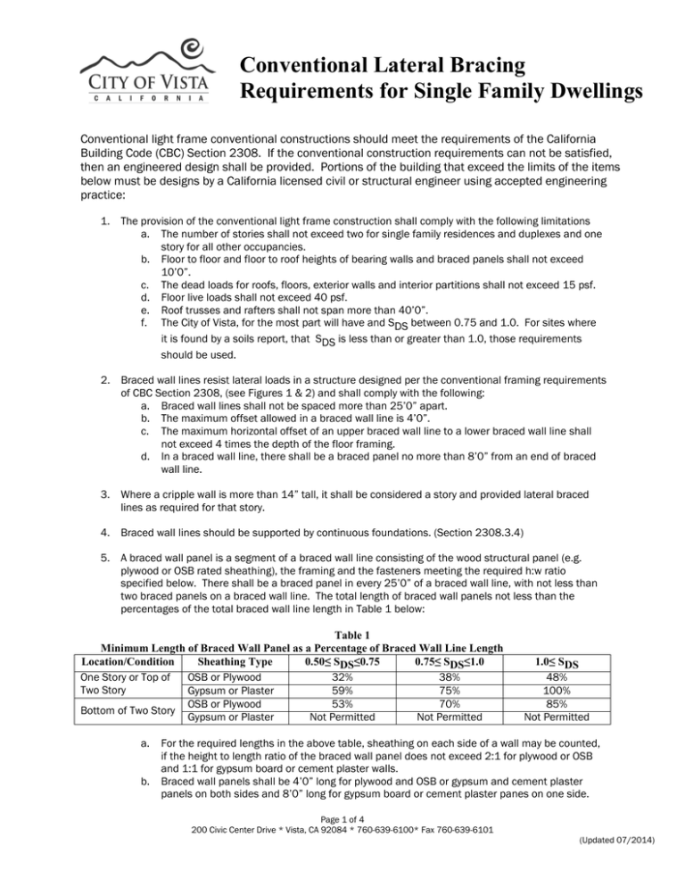
Conventional Lateral Bracing Requirements for Single Family Dwellings Conventional light frame conventional constructions should meet the requirements of the California Building Code (CBC) Section 2308. If the conventional construction requirements can not be satisfied, then an engineered design shall be provided. Portions of the building that exceed the limits of the items below must be designs by a California licensed civil or structural engineer using accepted engineering practice: 1. The provision of the conventional light frame construction shall comply with the following limitations a. The number of stories shall not exceed two for single family residences and duplexes and one story for all other occupancies. b. Floor to floor and floor to roof heights of bearing walls and braced panels shall not exceed 10’0”. c. The dead loads for roofs, floors, exterior walls and interior partitions shall not exceed 15 psf. d. Floor live loads shall not exceed 40 psf. e. Roof trusses and rafters shall not span more than 40’0”. f. The City of Vista, for the most part will have and SDS between 0.75 and 1.0. For sites where it is found by a soils report, that SDS is less than or greater than 1.0, those requirements should be used. 2. Braced wall lines resist lateral loads in a structure designed per the conventional framing requirements of CBC Section 2308, (see Figures 1 & 2) and shall comply with the following: a. Braced wall lines shall not be spaced more than 25’0” apart. b. The maximum offset allowed in a braced wall line is 4’0”. c. The maximum horizontal offset of an upper braced wall line to a lower braced wall line shall not exceed 4 times the depth of the floor framing. d. In a braced wall line, there shall be a braced panel no more than 8’0” from an end of braced wall line. 3. Where a cripple wall is more than 14” tall, it shall be considered a story and provided lateral braced lines as required for that story. 4. Braced wall lines should be supported by continuous foundations. (Section 2308.3.4) 5. A braced wall panel is a segment of a braced wall line consisting of the wood structural panel (e.g. plywood or OSB rated sheathing), the framing and the fasteners meeting the required h:w ratio specified below. There shall be a braced panel in every 25’0” of a braced wall line, with not less than two braced panels on a braced wall line. The total length of braced wall panels not less than the percentages of the total braced wall line length in Table 1 below: Table 1 Minimum Length of Braced Wall Panel as a Percentage of Braced Wall Line Length Location/Condition Sheathing Type 0.50≤ SDS≤0.75 0.75≤ SDS≤1.0 One Story or Top of OSB or Plywood 32% 38% Two Story Gypsum or Plaster 59% 75% OSB or Plywood 53% 70% Bottom of Two Story Gypsum or Plaster Not Permitted Not Permitted a. b. 1.0≤ SDS 48% 100% 85% Not Permitted For the required lengths in the above table, sheathing on each side of a wall may be counted, if the height to length ratio of the braced wall panel does not exceed 2:1 for plywood or OSB and 1:1 for gypsum board or cement plaster walls. Braced wall panels shall be 4’0” long for plywood and OSB or gypsum and cement plaster panels on both sides and 8’0” long for gypsum board or cement plaster panes on one side. Page 1 of 4 200 Civic Center Drive * Vista, CA 92084 * 760-639-6100* Fax 760-639-6101 (Updated 07/2014) 6. Braced wall panels are made up as follows: a. For braced wall panels of plywood or OSB construction: i. Plywood or OSB panels shall be 5/16” or thicker for 16” stud spacing and 3/8” thick for 24” stud spacing. (T-111 siding may be used, with consideration for these minimum thicknesses) ii. Plywood and OSB panels are nailed with 8d common or hot dipped galvanized nails at 6” O.C. to all plywood edges and 12” O.C. filed nailing. b. For braced panels of gypsum board construction: i. ½” or 5/8” gypsum board shall be used. ii. ½” gypsum board shall be nailed with 5d cooler nails at 7” O.C. and 5/8” gypsum board shall be nailed with 6d cooler nails at 4” O.C. iii. The gypsum board nailing shall be to all plates, studs and blocking. c. For cement plaster (stucco) braced wall panels: i. The stucco shall be 7/8” thick. ii. Expanded metal lath or woven wire lath is used. iii. Lath is nailed with No. 11 gauge nails, 1 ½” long with 7/16” heads or No. 16 gage staples with 7/8” long legs. iv. Nailing is at 6” O.C. to all plates, studs and blocking. d. Where a 4’0” minimum length is not feasible, alternate braced panels per Fig. 3 may be used as follows: i. The minimum length is 2’8” and sheathed with 3/8” plywood or OSB. ii. The sheathing is nailed with 8d common or galvanized nails at 6” O.C. at all wood structural panel edges and 12” O.C. at intermediate studs. iii. Two anchor bolts are provided in the alternate braced panel. iv. For panels in one story buildings, a hold down device adequate to resist 1,800 lbs of uplift at each end of the panel. v. In the first story of two story buildings, the panel is sheathed with plywood or OSB on each side, three anchor bolts are provided and hold down devices adequate to resist 3,000 lbs of uplift are provided at each end of the panel. vi. For calculating the length of braced wall panel, a 2’8” wide alternate panel shall be the equivalent of a 4’0” wide braced panel. e. Where an alternate panel is installed to a door or window opening, a portal frame (see Fig. 4) may be used as follows: i. The minimum length is 16” for one story and 24” for the first of two story conditions. ii. 3/8” plywood or OSB sheathing is applied to one face with 8d nails on a 3” grid as per the diagram. iii. A 3” by 11.25” net header extends over the top of the portal wall and is attached to the top plate with two rows of 16d sinker nails at 3” O.C. and 1,000 lb strap opposite of the sheathing. The header clear span shall not be less than 6’0” or greater than 18’0”. iv. The ends of the panels are anchored to the foundation with hold down devices adequate to resist 4,200 lbs. v. The far end of the portal frame header is either anchored to the foundations with a strap and hold down device adequate to resist 1,000 lbs or tied into another portal panel. vi. A 12” minimum deep footing with at least one #4 bar top and bottom is provided across the opening. f. For calculating the length of braced wall panel, these alternate panels shall be the equivalent of a 4’0” wide braced panel. g. Manufactured braced wall panels may be used, if the manufacturer’s approval listing is approved to be equivalent to conventional braced panels. h. Braced panels shall be provided with ½” or 5/8” anchor bolts at 6’0” O.C. for one story buildings and 4’0” O.C. for two story buildings. Anchor bolts shall be provided with 3”x3”x0.229” thick washwer on top of the sill plate. 7. Braced wall lines and braced wall panels shall be identified on the building plan similar to Figure 2 showing the location, length and type of braced wall panels. The illustration details the location and length of the braced wall panels and show compliance with the braced wall provisions as stated above. Page 2 of 4 Page 3 of 4 Page 4 of 4
