permanent mse retaining wall systems
advertisement

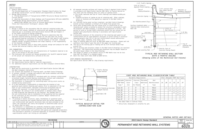
C.I.P. Traffic Railing NOTES Limit of Class 5 Applied Finish Coating SPECIFICATIONS: 1. General Specifications: 9. All exposed concrete surfaces will receive a Class 5 Applied Finish Coating The Florida Department of Transportation "Standard Specifications for Road in accordance with Specification Section 400. Refer to Typical Section on and Bridge Construction", Current Edition and Supplements as Amended. this sheet and the following notes for limits of applied finish: 2. Design Specifications: C.I.P. Junction Slab Top of Shoulder or (See Index Series Coping Elevation Roadway Pavement 6100) a. The inside, backside and top of Traffic Railings and Pedestrian/Bicycle a. Florida Department of Transportation (FDOT) "Structures Design Guidelines", Current Edition. Railings. Concrete Coping b. Exposed surfaces of coping on top of retaining wall. Other coatings, b. American Association of State Highway and Transportation Officials (AASHTO) colors or textures will be applied as required in the Wall Control "LRFD Bridge Design Specifications", Current Edition. Drawings. c. AASHTO-AGC-ARTBA Task Force 27 (Ground Modification Techniques), "Insitu Soil Improvement Techniques", January 1990. Soil Reinforcement (Typ.) 10. For concrete facing panel surface treatment, see Wall Control Drawings. Extend surface treatment a minimum of 6" below final ground line. Surface treatment when 11. Drive piles located within the soil volume prior to construction of the DESIGN CRITERIA: retaining wall, unless a method to protect the structure, acceptable to both required (See Construction 1. Design is based on the assumption that the material contained within the the Engineer and Wall Company, is proposed and approved in writing. The Note 10) reinforced soil volume, methods of construction and quality of prefabricated portion of piles or drilled shafts extensions within the soil volume will be materials are in accordance with Specification Section 548 and Chapter 3 wrapped with polyethylene sheeting in accordance with Specification of the FDOT’s Structures Design Guidelines. Section 459. 2. It is the responsibility of the Engineer of Record to determine that the Soil Volume 12. A structural extension of the connection of the retaining wall panel to soil reinforcement will be used whenever necessary to avoid cutting or excessive the factored bearing resistance of the foundation for that specific wall location. skewing (greater than 15) of the soil reinforcement around obstructions stability design, including foundation and slope stability, is the responsibility of the Engineer of Record. 1’-0" Min. 4’-0" Min. maximum factored bearing pressure shown for the wall does not exceed 3. The Wall Company is responsible for internal stability of the wall. External Limits of Proposed Final Ground Line (i.e., piles, pipes, manholes, drop inlets, etc.). 13. Steps in leveling pads will occur at MSE Wall panel interfaces. Panels will not cantilever more than 2" past the end of the upper tier leveling pad. 4. If there are manholes and/ or drop inlets present, design and analysis for both internal and external stability shall be considered. Top of 14. The top of the leveling pad or footing will be 2’-0" minimum below final Leveling Pad ground line. 2’-0" Min. Elevation 15. Top of leveling pad elevations shown in the Wall Control Drawings are maximum SOIL PARAMETERS: elevations. The constructed leveling pad elevations may be deeper based on 1. See Wall Control Drawings for soil characteristics of foundation material to be the panel layout shown in the shop drawings. used in the design of the wall system. Interior Face of Concrete Leveling Pad Concrete Facing Panels 16. The height of panels in the bottom course of MSE Walls must not be less 2. The Contractor will provide soil design parameters for backfill material based on the actual soil characteristics utilized at the site. TYPICAL MSE RETAINING WALL SECTION than half the height of a standard panel. WITH A TRAFFIC RAILING 17. Work this Index with Index 6100 & 6200 Series. (Showing Limits of the Reinforced Soil Volume) MATERIALS: SHOP DRAWING REQUIREMENTS: 1. Concrete Class: See Wall Control Drawings. See Specification Section 548 for shop drawing requirements. 2. See Specification Section 548 for material requirements. 3. For additional material requirements see the Wall Company’s General Notes. CONSTRUCTION: 1. Walls will be constructed in accordance with Specification Section 548 and Traffic Railing the Wall Company’s instructions. (Type Varies) 2. For location and alignment of retaining walls, see Wall Control Drawings. 3. If present, consider in design and analysis and locate manholes and drop inlets as shown on wall elevations. FDOT MSE RETAINING WALL CLASSIFICATION TABLE 4. Refer to Wall Control Drawings of individual walls for minimum reinforcement strip/mesh length, factored bearing resistance’s, minimum wall embedment Precast or Durability Requirements Other Allowable FDOT Wall Types C-I-P Coping and anticipated long term and differential settlements. Applicable Concrete Concrete Pozzolan Soil FDOT Wall Cover Class Additions? Reinforcement Type * (in.) for Panels ** Type 5. The Contractor is responsible for controlling water during storm events as needed during construction. 2" Min. 6. It is the Contractor’s responsibility to determine the location of any guardrail posts behind retaining wall panels. Prior to placement of the top Cover layer of soil reinforcement, individual reinforcing strips/mesh may be skewed (15 maximum) to avoid the post locations if authorized by Varies C-I-P Build-up Concrete Type 2A (Depth Varies) the Engineer. No cutting of soil reinforcement is allowed unless shown on Shop Drawings and approved by the Engineer. Any damage done to Dowel Bars 4D the soil reinforcement due to installation of the guardrail will be repaired 2 II No Metal Type 2B 2 IV No Metal Type 2C 3 IV No Metal Type 2D 3 IV Yes Metal Type 2E 3 IV No Plastic Type 2F 3 IV Yes Plastic 2A 2B 2C 2D 2E 2F by the Contractor at the Contractor’s expense. Repair method will be approved by the Engineer. 7. If existing or future structures, pipes, foundations or guardrail posts Precast Panel within the reinforced soil volume interfere with the normal placement of * See Data Table in Contract Plans. soil reinforcement and specific directions have not been provided on the plans, the Contractor will notify the Engineer to determine what course of action shall be taken. 8. The Contractor is responsible for gradually displacing upper layer(s) of TYPICAL BUILD-UP DETAIL FOR ** Silica fume, metakaolin or ultrafine fly ash. COPING/JUNCTION SLAB soil reinforcement downward (15 maximum from horizontal) to avoid cutting soil reinforcement and conflicts with paving and subgrade preparation. The Contractor’s attention is directed especially to situations where roadway superelevation and/or soil mixing are anticipated. GENERAL NOTES AND DETAILS REVISIONS DATE BY 01/01/11 GJM DESCRIPTION DATE 2010 Interim Design Standard BY DESCRIPTION New Index No. & Title (Previously Index 5300, Sheet 1 of 19); Changed Materials Notes, Construction Notes 11 & 14 and Shop Drawing note; Deleted Construction Note 9 and QPL Notes. PERMANENT MSE RETAINING WALL SYSTEMS Interim Date Sheet No. 01/01/11 1 of 1 Index No. 6020

