EVF Instructions
advertisement

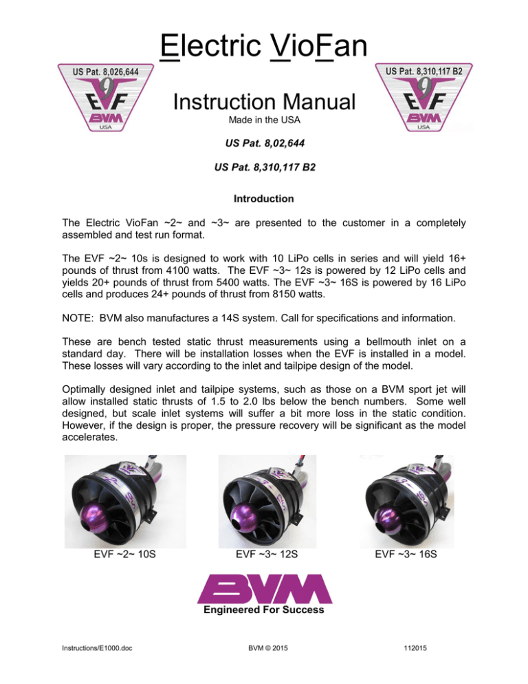
Electric VioFan Instruction Manual Made in the USA US Pat. 8,02,644 US Pat. 8,310,117 B2 Introduction The Electric VioFan ~2~ and ~3~ are presented to the customer in a completely assembled and test run format. The EVF ~2~ 10s is designed to work with 10 LiPo cells in series and will yield 16+ pounds of thrust from 4100 watts. The EVF ~3~ 12s is powered by 12 LiPo cells and yields 20+ pounds of thrust from 5400 watts. The EVF ~3~ 16S is powered by 16 LiPo cells and produces 24+ pounds of thrust from 8150 watts. NOTE: BVM also manufactures a 14S system. Call for specifications and information. These are bench tested static thrust measurements using a bellmouth inlet on a standard day. There will be installation losses when the EVF is installed in a model. These losses will vary according to the inlet and tailpipe design of the model. Optimally designed inlet and tailpipe systems, such as those on a BVM sport jet will allow installed static thrusts of 1.5 to 2.0 lbs below the bench numbers. Some well designed, but scale inlet systems will suffer a bit more loss in the static condition. However, if the design is proper, the pressure recovery will be significant as the model accelerates. EVF ~2~ 10S EVF ~3~ 12S EVF ~3~ 16S Engineered For Success Instructions/E1000.doc BVM © 2015 112015 Safety Warnings • DO NOT attempt to run this fan system outside of a BVM (or similar designed) airframe. The inlet and tailpipe incorporated in our product offers you protection from the spinning rotor. The bench testing has been accomplished during the development and manufacture of this product. • DO NOT disassemble the shroud and stator system. It is properly aligned at the factory. • DO NOT disassemble the rotor unit. It is properly assembled and balanced at the factory. If a blade becomes damaged, return the entire EVF to the factory for repair. It is unlikely that only one blade can be damaged while the rotor is spinning. • DO NOT allow paint to get on to the rotor blades. This could cause an out of balance condition that could cause the rotor to vibrate and possibly come loose. • KEEP loose objects away from the inlet and tailpipe. Point the tailpipe toward an open area away from people or property when the engine is running. • INSPECT the EVF frequently. If any parts become damaged, return the unit to the factory for repair. • Absolutely, keep your hands away from the spinning rotor. Never attempt to hand hold the unit with the batteries attached such that the rotor could spin under power. Disclaimers The user of the EVF system should be an experienced modeler who can exercise mature judgment as to the proper application and operation of this high performance unit. THE USER OF THE EVF SHALL ASSUME ALL RISK AND LIABILITY IN CONNECTION THEREWITH. THERE ARE POSSIBLE HAZARDS ASSOCIATED WITH NOT ADHERING TO RECOMMENDS PROCEDURES AND/OR WITH THE USE OF DIFFERENT MOTOR/FAN COMBINATIONS. Products sold by BVM are designed to work as a complete system in a BVM airframe and are extensively flight tested as such. Therefore, structural modifications, shoddy workmanship, neglect of periodic maintenance checks by the consumer, or the use of another motor or fan in a BVM airframe not specified by BVM could lead to an unsafe and potentially dangerous operation. BVM ASSUMES NO RESPONSIBILTY OR LIABILITY FOR MISUSE OF ITS PRODUCTS AS HEREIN DESCRIBED. If you install a BVM EVF in an airframe with improperly designed inlet ducts and/or tailpipes, expect to lose as much as 50% of the advertised thrust. BVM designs respect the physics of airflow. Instructions/E1000.doc BVM © 2015 1 112015 EVF Power Batteries The EVF ~2~ 10s is powered by (2) 5S 2P 6600mAh Saddle Cells TM. These (2) packs are connected in series with a BVM Power Plug 2 (BVM #E1000-22). An Additional 10s power configuration is comprised of (2) 4s and (1) 2s 6600 batteries and utilizes a Power Plug 3. The EVF ~3~ 12s is powered by (3) 4s 6600 or 7700 Saddle Cells TM. These 3 packs are connected in series with a BVM Power Plug 3 (BVM# E1000-23). The EVF ~3~ 16S is powered by (4) 4S 7700mAh Saddle Cells. These 4 packs are connected in series with a Power Plug 4+. Note: Lithium Polymer batteries should be stored at “Storage Charge” when not in use. This is how the batteries come from the manufacture. Use a modern charger that has a “storage” feature. Power Plug 4+ See BVMJets.com/electric power for the most up-to-date battery choices. Instructions/E1000.doc BVM © 2015 2 112015 The E.S.C. Connection 10S and 12S System CAUTION: Avoid wearing metal rings on your fingers when operating high powered electric models. Become familiar with your brand of Radio Control System and know that the low throttle signal is properly set with the throttle stick at idle and the trim lever full AFT. It could be hazardous to have this channel reversed. Connect the E.S.C. (small plug) to the receiver throttle channel. Be certain to properly orient the positive pin to the positive receptacle and likewise for the negative pin. Aim the negative pin at the plastic side of the receptacle and in one smooth swift curved path action, make the connection. A small spark will occur, after the second series of E.S.C. “beeps” is heard, the EVF is powered up. You can check this with a small advance of the throttle lever. Description of EVF Parts The fan rotor is a 4.6” diameter unit that is designed for optimum in-flight performance. It is injection molded of the very latest and strongest carbon fiber filled engineering plastic. The maximum take-off RPM on the 10s is 25,500, the 12s runs at 27,500 RPM and the 16S runs at 32,000 RPM. The maximum tested RPM of the rotor is considerably above this. The rotor is meticulously dynamically balanced at BVM and test run for smooth operation. Please do not attempt to disassemble the rotor and back plate system. Specific fixtures and tools are required to remove the rotor. If a blade is chipped from ingesting a foreign object, return the EVF to BVM for proper repair, balance, and test run. Caution: An out-of-balance rotor could cause it to break loose from its retaining bolt. Do not attempt to run a damaged rotor. For 16S, see BVM Manual # I5300e-02.docx Instructions/E1000.doc BVM © 2015 3 112015 The Shroud, stator, and Center Body Assembly The shroud and stators are injection molded from carbon fiber filled engineering plastic. The motor holding center body is a two-part assembly that is precision machined from Aluminum. These parts are assembled at BVM and the fan track area is lathe turned to be concentric with the motor axis. Do not adjust the screws that anchor the stators to the center body. 4 Stator System of EVF ~2~ 10S FAN TRACK AREA 12 Stator System of EVF ~3~ 12S and 16S The Brushless Motor The motors are made by Neutronics specifically for BVM and have a few special BVM innovated features exclusive to our applications. These motors are optimized in design to be very efficient and cool running in the EVF unit. Instructions/E1000.doc BVM © 2015 4 112015 The ESC The Castle Creations ESC controller has had the parameters set at BVM to properly time the motor and have the correct protection values for low voltage. The ESC wires are soldered to the motor at BVM to fit inside the aft center body fairing for enhanced cooling. • • • • • • • • • • • Settings for an EVF 10s: Cutoff voltage: 30.0 volts Cutoff type: Hard Direction: Forward Brake strength: 0% disabled Throttle type: Fixed Soft Start: Medium Motor Timing: High Current Limiting: Normal PWM rate: 12Khz Power Beep: On Logging: 5 Sample/sec – all • • • • • • • • • • • Settings for an EVF 12s: Cutoff voltage: 36.0 volts Cutoff type: Hard Direction: Forward Brake strength: 0% disabled Throttle type: Fixed Soft Start: Medium Motor Timing: High Current Limiting: Normal PWM rate: 12Khz Power Beep: On Logging: 5 Sample/sec – all Settings for an EVF 16s: These settings are accomplished @ BVM NOTE: See special instructions for the EVF ~3~ 16S doc #I5300e-02.docx The Aft Fairing The Aft Fairing is a hand layed part of epoxy fiber glass and Kevlar. This vital part functions as an aerodynamic fairing and cooling shroud for the motor and ESC. The ESC power and battery wires exit at the top with a foam rubber plug glued into position to avoid a thrust loss. The aft fairing is secured to the aluminum center body with four #2 x 1/4” socket button head screws with a drop of Zap Z-42 on each screw. The Kevlar band inside the fairing protects the area from wear. Instructions/E1000.doc BVM © 2015 5 112015 Foam inserts There is a foam insert that is installed in the top part of the aft fairing where the wires exit. This eliminates a thrust loss and allows the cooling airflow to exit at the rear of the fairing. A few drops of C.A. secure the foam insert. The plastic coaming on the top of the fairing protects the power wires from chaffing and helps to contain the Mylar Thrust Tube. FOAM INSERT PLASTIC COAMING EVF Mounts A soft mounting system is supplied that also offers a convenient method to mount the EVF to the wood rails in the model. Grind a slight chamfer on the end of the screws. Clear threads with a 4-40 nut. The 4-40 threaded holes in the wood mounts can be treated with Zap C.A. then tapped again. Instructions/E1000.doc BVM © 2015 6 112015 Low Voltage Warning in Flight How to Respond The Castle Creations Edge Lite HV160 controllers feature an adjustable minimum voltage protection feature. It can be set as desired using the Phoenix link USB cable. The BVM factory setting for a 10s system is 30 volts, for a 12s system the setting is 36 volts. If a power surge causes the voltage to drop to this level the unit will shut off the motor. This is an in-flight warning that the batteries are close to the maximum depletion level. Simply retard the throttle and throttle trim for a second, then advance again to a low power setting and the motor will restart. Land ASAP utilizing minimum power. Castle Creations Edge Lite HV160 Error Codes: BEEPS ISSUE 1 Start Failure: The motor was jammed or locked Low Voltage Cutoff: The batteries are likely discharged. Check that the batteries are fully charged and that the Phoenix detects the proper number of cells at power up Over-Current: Current draw exceeded the safe capacity of the controller. Reduce the current draw by changing to a fewer number of cells Motor Anomaly: Controller encountered abnormal motor behavior such as physical interference, etc. May also indicate lost synchronization or magnetic overload within the motor. Radio Signal: Signal from the receiver is corrupt or non-existent. Check transmitter and receiver. Over temperature 2 3 4 5 6 For the EVF ~3~ 12SE and 16S units see special instructions that come with these EVF's Instructions/E1000.doc BVM © 2015 7 112015 Radio Set-Up and 1st Flight Tips Reduced Power Setup for maximum flight time Activate a mix switch on your transmitter and adjust the parameters such that the full throttle position yields about 80% of the available power. An Amp Clamp (BVM# V-ETMA220) is necessary to select the power settings. A 10s unit can be set to 90 amps, a 12s unit can be set at about 95 amps. Use this full throttle position during flight in place of maximum power as much as possible. Select the mix switch to the full power position for impressive vertical climbs or high speed passes. Take-offs from paved run ways can be accomplished with reduced power. This technique conserves battery energy and allows longer flight times. Cruise power is achieved with the throttle stick at the mid position. This provides about 7-8 lbs. of thrust while consuming about 25-30 amps. Throttle Slow Technique Activate the “Throttle Slow” feature on your transmitter and set it for a 2 second transition time for a full movement of the throttle stick. This procedure will also conserve energy usage and reduce voltage spikes. Idle Trim Set-up Set the idle trim adjustment on your transmitter to switch the EVF motor on and off at its mid position. The upper half of the trim lever travel then adjusts the idle RPM. The minimum sustainable RPM is about 3500, which is equal to about ½ lb. of thrust. We operate with the throttle trim full aft. When the stick is aft, the motor is off. Transmitter travel adjust settings: Throttle ATV (DSM radio) High __85%___ Low __ 75%___ These values will vary with type of radio. The “High” setting should be such that when the throttle is reduced from the full power position, there is a corresponding reduction in fan rpm. The “Low” setting can be adjusted such that at the mid throttle trim position, the fan is running at its lowest rpm and will turn off by reducing the trim a bit more. This allows the fan to be an air brake for landing touchdown and roll out. Instructions/E1000.doc BVM © 2015 8 112015 How to know that your EVF is putting out its maximum potential at full throttle? It is a sound that you get used to hearing and AMP Clamp (BVM# V-ET-MA220) measurement. All EVF 10S and 12S systems will yield 105-115 amps at full power in a proper model installation. Always check the battery pack voltage before a flight. The packs should be within .1 volt of each other. EVF Flight Profile To start with, you can’t takeoff and fly for 5 minutes at full power. This could ruin the Lipo batteries and make for a very expensive flight. There is a given amount of energy stored in the batteries. An ideal flight profile will consume about 80% of the battery capacity. For a 6600 system, the ideal flight would consume 5200 or less and the battery temperature would be 100°-110°F at the end of the flight. The battery manufacturers consider these numbers to be safe and one should expect a high cycle life when staying within these parameters. So, to stay within the 80% margin, make the first flights with conservative power use, recharge the batteries, and then make time and power usage adjustments accordingly for following flights. For the first flight – pick a low wind day, set your transmitter timer to 5:00. Start the timer at the beginning of the take-off roll. Plan to touch down at 5 minutes. At 15-20 seconds after lift-off, reduce throttle to ¾ position for a cruise climb with gear and flaps up. During the flight, use a 50/50 mix of full throttle for high speed passes and vertical maneuvers, and ½ throttle for cruising fly-bys and turnarounds. The landing pattern can be flown with ½ throttle, gear and flaps down and then power off for the final glide path and flared touchdown. NOTE: Grass field operations will consume more power to taxi out and back. After you recharge the batteries and determine the % of capacity utilized for the first flight, you can adjust the flight time and profile accordingly. BVM’s experience allows us to set the flight time to 6 minutes for a 10s system (6600mAh), 6 minutes for a 12s system (6600mAh) and 7 minutes with 7700mAh batteries. The total motor run time will be about 1 minute more to include taxi out and back. Note the battery temps and voltage after each flight. Some electric jet flyers like to keep records of each battery cycle. In the long run, the knowledge gained will be useful. Instructions/E1000.doc BVM © 2015 9 112015 Warranty Warranty is applicable to first owner only and for a period of 2 years from date of purchase as recorded at BVM. If unit is purchased from a dealer, send serial number and date of purchase to BVM. Items Covered Under Warranty: Parts as listed here and labor to repair/replace: • Electric Motor - all components • Fan Blades, Spinner, Shroud, Stator Fins, Aft Center Body, and Rotor retention hardware • Castle Creation – Edge Lite HV160 * 1 year per Castle Creations warranty Items Not Covered: • Deans Connector Warranty Void If: Crash damage, drop damage, paint on rotor blades, operated with batteries not recommended by BVM or improper cell count, reverse polarity connection, foreign object ingested, any disassembly of the unit or tampering with the factory settings, installed in airframe with improper inlet design, or water damage. The BVM Electric VioFan systems must be operated according to the appropriate manuals supplied by BVM. Instructions/E1000.doc BVM © 2015 10 112015


