a valve-less micro pump with pzt diaphragm
advertisement

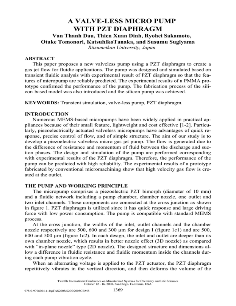
A VALVE-LESS MICRO PUMP WITH PZT DIAPHRAGM Van Thanh Dau, Thien Xuan Dinh, Ryohei Sakamoto, Otake Tomonori, KatsuhikoTanaka, and Susumu Sugiyama Ritsumeikan University, Japan ABSTRACT This paper proposes a new valveless pump using a PZT diaphragm to create a gas jet flow for fluidic applications. The pump was designed and simulated based on transient fluidic analysis with experimental result of PZT diaphragm so that the features of micropump are reliably predicted. The experimental results of a PMMA prototype confirmed the performance of the pump. The fabrication process of the silicon-based model was also introduced and the silicon pump was achieved. KEYWORDS: Transient simulation, valve-less pump, PZT diaphragm. INTRODUCTION Numerous MEMS-based micropumps have been widely applied in practical appliances because of their small feature, lightweight and cost effective [1-2]. Particularly, piezoelectrically actuated valveless micropumps have advantages of quick response, precise control of flow, and of simple structure. The aim of our study is to develop a piezoelectric valveless micro gas jet pump. The flow is generated due to the difference of resistance and momentum of fluid between the discharge and suction phases. The design and simulation of the pump are performed corresponding with experimental results of the PZT diaphragm. Therefore, the performance of the pump can be predicted with high reliability. The experimental results of a prototype fabricated by conventional micromachining show that high velocity gas flow is created at the outlet. THE PUMP AND WORKING PRINCIPLE The micropump comprises a piezoelectric PZT bimorph (diameter of 10 mm) and a fluidic network including a pump chamber, chamber nozzle, one outlet and two inlet channels. These components are connected at the cross junction as shown in figure 1. PZT diaphragm is utilized since it has quick response and large driving force with low power consumption. The pump is compatible with standard MEMS process. At the cross junction, the widths of the inlet, outlet channels and the chamber nozzle respectively are 500, 600 and 300 µm for design I (figure 1c1) and are 500, 600 and 500 µm (figure 1c2). In each design, the inlet and outlet are deeper than its own chamber nozzle, which results in better nozzle effect (3D nozzle) as compared with “in-plane nozzle” type (2D nozzle). The designed structure and dimensions allow a difference in fluidic resistance and fluidic momentum inside the channels during each pump vibration cycle. When an alternating voltage is applied to the PZT actuator, the PZT diaphragm repetitively vibrates in the vertical direction, and then deforms the volume of the Twelfth International Conference on Miniaturized Systems for Chemistry and Life Sciences October 12 - 16, 2008, San Diego, California, USA 978-0-9798064-1-4/µTAS2008/$20©2008CBMS 1369 Inlet 0.5mm PZT disc Cover Outlet Inlet Cross junction Pump chamber Inlet Chamber nozzle 0.5mm Outlet 0.6mm 0.3mm (c1) Outlet Chamber nozzle 0.5mm Outlet 0.6mm Channel part (a) Outlet port (b) (c2) Inlet 0.5mm Figure 1. Illustration of the micro pump. Channel design (a), cross-views of the pump (b) and dimensions of cross junctions (c) Inlet Inlet Outlet Junction (a) First Intake Inlet Outlet Inlet Junction Outlet Inlet (b) First Emission Inlet Junction Inlet (c) Second Intake Outlet Junction Inlet (d) Second Emission Figure 2. Working principle of the micro pump pump chamber, as shown in figure 2. During the first downward move of the diaphragm, gas is obtained into the pump chamber from both inlets and outlet (figure 2a). In the consequent upward move of the diaphragm, most gas is expelled at high velocity from chamber nozzle, through the cross junction, to the outlet while few of gas runs into the orthogonally connected inlet channels (figure 2b). In the second downward motion of the diaphragm (figure 2c), the gas is suck into the pump chamber due to the low pressure here. At this moment, the resistance and forward momentum of the fluid in outlet are lager than those in the inlet channels. This results in that the gas entering pump chamber is dominantly from the inlet channels. As the progress continues, the gas flows from the inlets to outlet channels. SIMULATION AND EXPERIMENTS The PZT diaphragm oscillates at its resonant frequency of 7000 Hz. Because of the symmetry, one half of the pump is simulated by the use of ANSYS-FLUENT 6.3. The motion of PZT diaphragm is converted to time-dependent velocity for fluidic field. Time step is taken as one-twentieth of the PZT diaphragm vibrating cycle. Figure 3(a) shows the time averaged velocity profiles in the inlet and outlet channels for design I. The color represents the relative magnitude of velocity on each cross section. The time-dependent flow rate through the outlet in figure 3(b) shows that smaller cross-junction results on better pump performance. Design I creates mean flow rate of 153 ml/min which is 3 times larger than that of design II Twelfth International Conference on Miniaturized Systems for Chemistry and Life Sciences October 12 - 16, 2008, San Diego, California, USA 1370 Vibration PZT 7mm Symmetry plane 10mm Inlet (a) 30 PZT diaphragm Inlet outlet (i) (ii) Volume Flow (ml/min)) 25 Outlet cross junction 20 (iii) 15 10 (c) (iv) 5 (d) inlet 0 0 10 20 30 40 Applied voltage (Vp-p) (e) inlet 7mm 50 Figure 3. Time average result of design I (a), transient mass flow rate at the outlet (b), “blown away particle” (c), measured volume flow of design II (d), fabricated silicon part of design I (e) (50ml/min). Therefore, the optimized dimensions can be achieved from figure 1(c1). A prototype of design II was fabricated by conventional machining on PMMA material due to its large dimensions. After sealing with PMMA caps, the PZT diaphragm is assembled and the test is carried out. Gas flow with high velocity at the outlet was observed by “blown- away particles” as shown in figure 3(c). Figure (3d) shows the variation of the measured flow rate of this pump against applied voltage on PZT actuator. Due to its small dimension, design I has to be fabricated by MEMS technology. In order to achieve 3D nozzle effect, the silicon part was divided into 3 layers. Each layer was fabricated by DRIE process and then bonded together before sealed with PMMA caps and PZT diaphragm as shown in figure 3(e), the insets (ii, iii, iv) show the individual parts before assemble in (i). Testing experiments of design I is on progress. ACKNOWLEDGEMENTS This study is supported by the Japan Society for the Promotion of Science (JSPS) through the JSPS Postdoctoral Fellowship for Foreign Researcher. REFERENCES [1] P. Woias, Micropumps – past, progress and future prospects, Sensors and Actuators B. 105, pp.28-38, (2000). [2] D. J. Laser and J. G. Santiago, A review of micropumps, J. Micromech. Microeng. 14, R35–R64, (2004). Twelfth International Conference on Miniaturized Systems for Chemistry and Life Sciences October 12 - 16, 2008, San Diego, California, USA 1371


