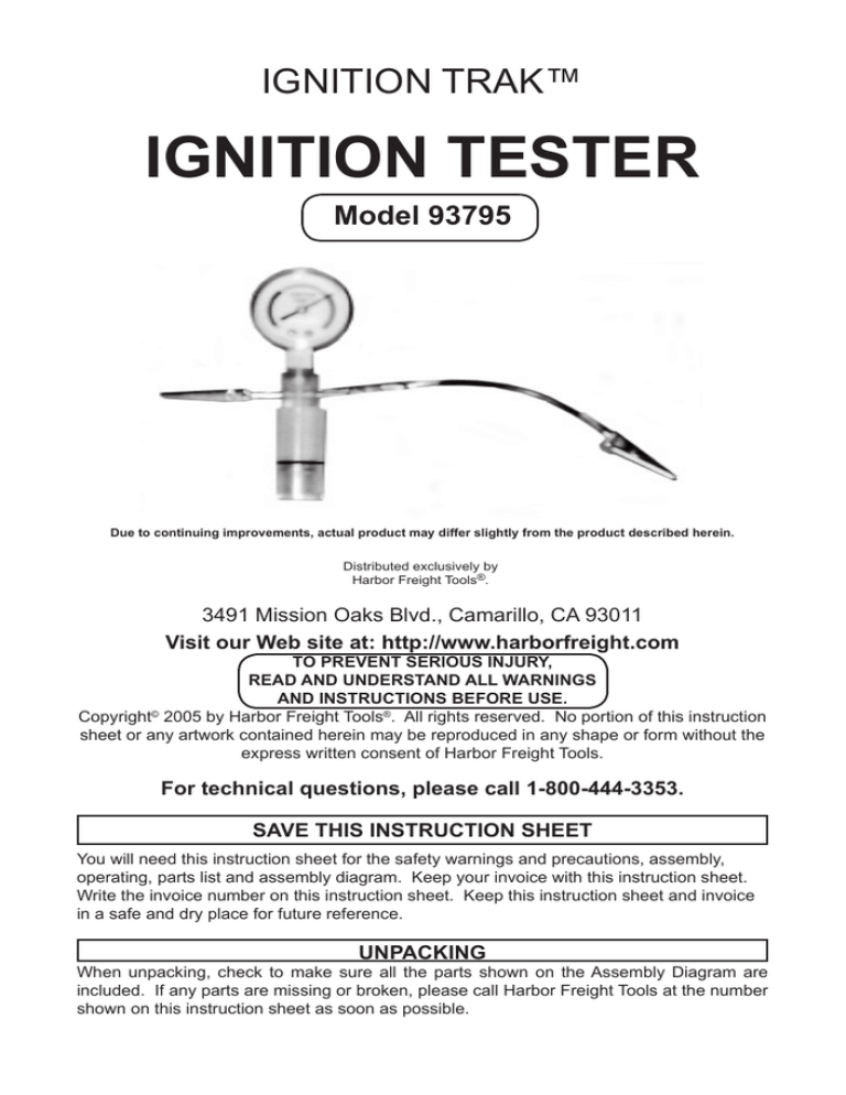
Ignition Trak™
IGNITION TESTER
Model 93795
Due to continuing improvements, actual product may differ slightly from the product described herein.
'LVWULEXWHGH[FOXVLYHO\E\
+DUERU)UHLJKW7RROV
3491 Mission Oaks Blvd., Camarillo, CA 93011
Visit our Web site at: http://www.harborfreight.com
TO PREVENT SERIOUS INJURY,
READ AND UNDERSTAND ALL WARNINGS
AND INSTRUCTIONS BEFORE USE.
Copyright© 2005 by Harbor Freight Tools®. All rights reserved. No portion of this instruction
sheet or any artwork contained herein may be reproduced in any shape or form without the
express written consent of Harbor Freight Tools.
For technical questions, please call 1-800-444-3353.
SAVE THIS INSTRUCTION SHEET
You will need this instruction sheet for the safety warnings and precautions, assembly,
operating, parts list and assembly diagram. Keep your invoice with this instruction sheet.
Write the invoice number on this instruction sheet. Keep this instruction sheet and invoice
in a safe and dry place for future reference.
UNPACKING
When unpacking, check to make sure all the parts shown on the Assembly Diagram are
included. If any parts are missing or broken, please call Harbor Freight Tools at the number
shown on this instruction sheet as soon as possible.
SAFETY WARNINGS AND PRECAUTIONS
1.
WARNING! Avoid high voltage shock. Do not handle the Ignition Tester while
the tool is in operation.
2.
CAUTION! Make sure the Ignition Tester does not get caught in rotating fans,
flywheels, belts, and other moving parts of the engine.
3.
When preparing a vehicle for ignition testing, make sure the vehicle’s transmission
is placed in “PARK” or “NEUTRAL” and the emergency brake is applied.
4.
Always keep hands, fingers, and body away from the moving parts and hot parts
of the engine.
5.
Dress properly. Do not wear loose clothing or jewelry as they can be caught in moving
parts. Wear restrictive hair covering to contain long hair.
6.
Do not use this product if under the influence of alcohol or drugs. Read warning
labels if taking prescription medicine to determine if your judgement or reflexes are
impaired while taking drugs. If there is any doubt, do not use this product.
7.
Replacement parts and accessories: This product must be repaired and serviced
by a qualified service technician only. When this product is serviced, only identical
replacement parts should be used. Use of any other parts will void the warranty. Only
use accessories intended for use with this product.
8.
Prior to using this product, make sure to read and understand all instructions
and safety precautions as outlined in the engine manufacturer’s diagnostic/repair
manual.
9.
Use the Ignition Tester in a well ventilated area. Do not operate in a closed area or
in a poorly-ventilated area. When running, an engine produces carbon monoxide,
a colorless, odorless, toxic fume that, when inhaled, can cause serious personal
injury or death.
10. Keep this product away from children. This product is not a toy.
11.
WARNING! People with pacemakers should consult their physician(s) before using
this product. Electromagnetic fields in close proximity to a heart pacemaker could cause
interference or failure of the pacemaker. In addition, people with pacemakers should
adhere to the following: Caution is necessary when near the coil, spark plug cables, or
distributor of a running engine. The engine should always be off if adjustments are to
be made to the distributor.
12.
WARNING! The warnings and cautions discussed in this instruction sheet cannot
cover all possible conditions and situations that may occur. It must be understood by
the operator that common sense and caution are factors which cannot be built into this
OPERATING INSTRUCTIONS
1.
Remove all of the engine’s spark plugs.
2.
Remove the Lower Cup (1) from the Ignition Tester. Wet the O-Ring (2) on Cylinder (3)
with a drop of water to make the Cup easier to move in the Cylinder (3) of the Ignition
PAGE 2
For technical questions, please call 1-800-444-3353.
SKU 93795
REV 08d
Tester. Use only water. Do not use oil, grease, solvents, cleaners, or any other
agent as a lubricant as damage to the Ignition Tester will occur.
3.
Pressurize the Ignition Tester by inserting the Cup (1) into the Cylinder (3), using a twisting/sliding motion. Make sure not to damage the O-Ring (2). Move the Cup up toward
Alligator Clips (4, 5) until the Gauge (6) pointer reaches the upper end of the green band
of the Gauge. Do not force the pressure to rise beyond the end of the green band.
4.
Connect the Ground Alligator Clip (4) to a clean metal engine ground location so the
Ignition Tester doesn’t move when the engine is cranked.
5.
Connect the Ignition Alligator Clip (5) to the spark plug wire, making sure the Clip has firm
contact with the metal terminal within the rubber boot of the spark plug wire. For engines
with one coil for each engine cylinder, ground the coil wires not being tested to prevent
coil damage. Make sure the metal ground surface is clean and free of corrosion.
6.
Crank the engine with its rope or starter while watching the arc in the clear plastic body
of the Cylinder (3) of the Ignition Tester. If the arc is BLUE and firing on a timed, consistent basis the engine’s ignition system is in proper working order. The arcing will occur
between the two studs to which the Alligator Clips (4, 5) are attached.
TROUBLESHOOTING
1.
If there was no arc, or an occasional arc, reduce the test pressure with the engine
stopped to about the middle portion of the green band on the Gauge (6) by applying a
slight outward twisting force to the Cup (1). Then, again crank the engine while noting
the condition of the arc or lack of an arc.
2.Repeat Step #1 in this section, reducing the test pressure to the lower portion of the
green band and into the yellow and red bands, or until the arc produces a constant
“timed” spark.
DIAGNOSIS AND CORRECTION PROCEDURES
1.
Using the the color or presence of a spark and the matching color band on the gauge,
refer to the following problems and their solutions:
If there is a blue spark and the pressure gauge reads Green: The system is operating
normally.
If there is a yellow spark and the pressure gauge reads Green: The system is only
operating marginally. Clean all connections, reduce pressure, and retest.
If there is a blue or yellow spark and the pressure gauge reads Yellow: The system
is only operating marginally. Clean all connections and retest.
If there is a blue or yellow spark and the pressure gauge reads Red: There is a weak
ignition coil.
If there is an orange or red spark and the pressure gauge reads Green: The points or
connections are dirty and/or corroded. Clean or replace the points and the electrical
connections. The condensor may also be faulty.
If there is an orange or red spark and the pressure gauge reads Yellow: There is a
weak ignition coil.
If there is an orange or red spark and the pressure gauge reads Red: There is a
faulty ignition coil and/or condensor.
REV 02/07
SKU 93795
For technical questions, please call 1-800-444-3353.
PAGE 3
If there is no spark, but the arc color indicated is Green: Reduce test pressure to “yellow” range and repeat test.
If there is no spark, but the arc color indicated is Yellow: Replace the points and
condensor. Then retest to check for proper coil operation.
If there is no spark, but the arc color indicated is Red: There is a faulty ignition coil.
Replace or service the coil.
2.
If the engine has one coil for each engine cylinder (as with some outboards and stationary engines) repeat Steps #3 through #6 in the “Operating Instructions” section for each
cylinder, making sure the coils not being tested have their spark plug wires grounded.
3.
If the engine is equipped with a “sealed” solid state ignition system and all external connections are clean and secure, the solid state module should be replaced.
PARTS LIST & ASSEMBLY DIAGRAM
Part
Description
Qty Part
Description
Qty
1
Cup
1
4
Ground Alligator Clip
1
2
O-Ring
1
5
Ignition Alligator Clip
1
3
Cylinder
1
6
Gauge
1
GROUND
ALLIGATOR
CLIP
(4)
GAUGE (6)
IGNITION
ALLIGATOR
CLIP
(5)
CYLINDER (3)
CUP (1)
O-RING (2)
NOTE:
Some parts are listed and shown for illustration purposes only,
and are not available individually as replacement parts.
PLEASE READ THE FOLLOWING CAREFULLY
THE MANUFACTURER AND/OR DISTRIBUTOR HAS PROVIDED THE PARTS LIST AND ASSEMBLY DIAGRAM IN
THIS MANUAL AS A REFERENCE TOOL ONLY. NEITHER THE MANUFACTURER OR DISTRIBUTOR MAKES ANY
REPRESENTATION OR WARRANTY OF ANY KIND TO THE BUYER THAT HE OR SHE IS QUALIFIED TO REPLACE
ANY PARTS OF THE PRODUCT. IN FACT, THE MANUFACTURER AND/OR DISTRIBUTOR EXPRESSLY STATES
THAT ALL REPAIRS AND PARTS REPLACEMENTS SHOULD BE UNDERTAKEN BY CERTIFIED AND LICENSED
TECHNICIANS, AND NOT BY THE BUYER. THE BUYER ASSUMES ALL RISKS AND LIABILITY ARISING OUT OF HIS
OR HER REPAIRS TO THE ORIGINAL PRODUCT OR REPLACEMENT PARTS THERETO, OR ARISING OUT OF HIS
OR HER INSTALLATION OF REPLACEMENT PARTS THERETO.
REV 02/07
PAGE 4
For technical questions, please call 1-800-444-3353.
SKU 93795


