TP-011209
P.O. Box 55
Cheswick, PA 15044
phone: 724-274-5430
fax: 724-274-5448
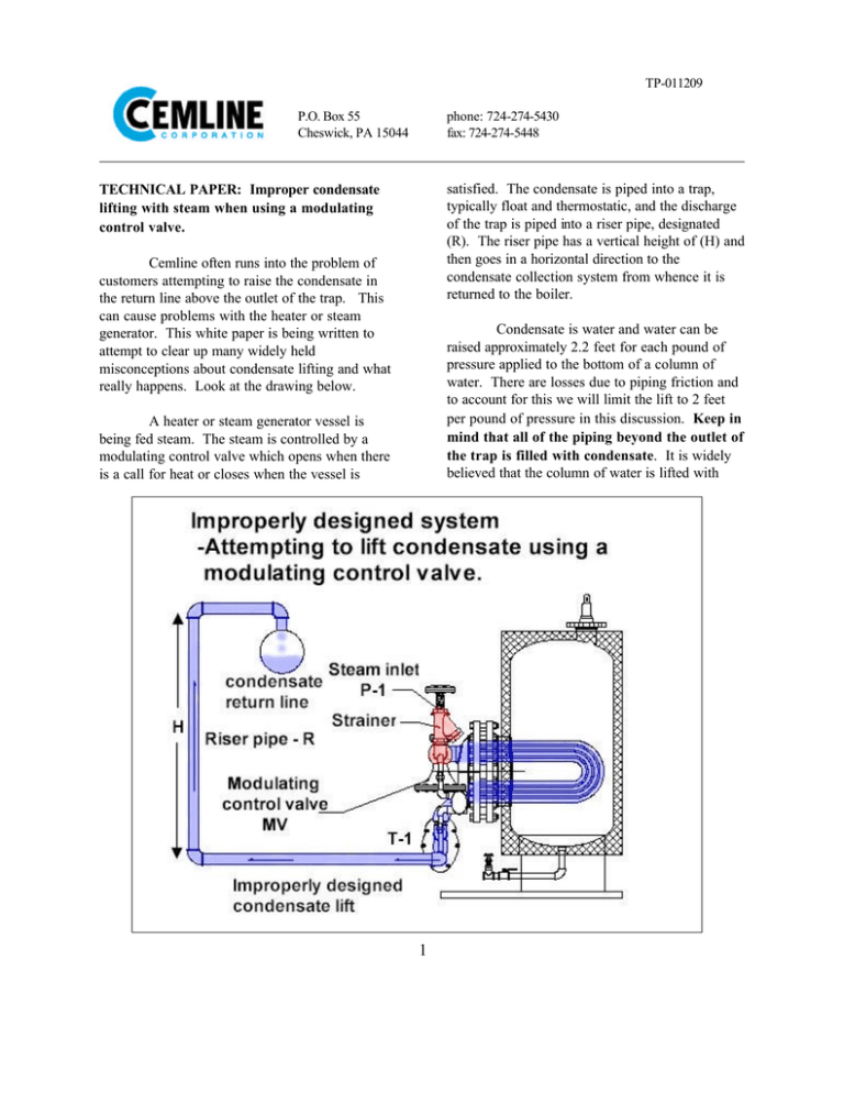
satisfied. The condensate is piped into a trap,
typically float and thermostatic, and the discharge
of the trap is piped into a riser pipe, designated
(R). The riser pipe has a vertical height of (H) and
then goes in a horizontal direction to the
condensate collection system from whence it is
returned to the boiler.
TECHNICAL PAPER: Improper condensate
lifting with steam when using a modulating
control valve.
Cemline often runs into the problem of
customers attempting to raise the condensate in
the return line above the outlet of the trap. This
can cause problems with the heater or steam
generator. This white paper is being written to
attempt to clear up many widely held
misconceptions about condensate lifting and what
really happens. Look at the drawing below.
Condensate is water and water can be
raised approximately 2.2 feet for each pound of
pressure applied to the bottom of a column of
water. There are losses due to piping friction and
to account for this we will limit the lift to 2 feet
per pound of pressure in this discussion. Keep in
mind that all of the piping beyond the outlet of
the trap is filled with condensate. It is widely
believed that the column of water is lifted with
A heater or steam generator vessel is
being fed steam. The steam is controlled by a
modulating control valve which opens when there
is a call for heat or closes when the vessel is
1
TP-011209
P.O. Box 55
Cheswick, PA 15044
phone: 724-274-5430
fax: 724-274-5448
steam and that the riser pipe is filled with steam.
Not true, the riser pipe is always filled with
condensate. When the trap opens to discharge
condensate any steam pressure behind the trap
provides the motive power to push the column of
water up. Since the trap is designed to let
condensate out and keep steam in only condensate
will be discharged from the trap and into the riser
pipe (R).
1. Water hammer as a result of condensate
flashing when the control valve opens again and
steam is introduced into the steam coil.
2. Corrosion from the inside of the tubes of the
coil due to the aggressive nature of some
condensate.
3. Erratic temperature or pressure control due to
heat being transferred from hot condensate into
the fluid in the vessel.
Let us make a theoretical example.
Looking at the drawing if the steam inlet pressure
is at 15 psig pressure (P-1) going into a
modulating control valve (MV). The steam goes
though a submerged coil and any condensate
formed is discharged through trap (T-1). At 15
psig steam prior to the control valve (P-1) and the
height of the riser pipe is 6 feet, as long as the
pressure in the tubes of the submerged coil is
greater than 3 psig there is enough pressure to
discharge all of the condensate formed from the
coil. As the vessel’s pressure or temperature is
satisfied the valve (MV) will begin to modulate
closed. When the valve (MV) closes the pressure
in the coil will begin to drop and eventually will
become 0 psi. As soon as the pressure in the coil
head becomes less than 3 psi there is no longer
enough motive power to raise the column of
condensate in the riser pipe (R) and any further
condensing steam will accumulate in the coil head
and in the tubes of the coil. If there is no check
valve in the riser line the condensate in the riser
pipe will back feed into the coil until the level of
condensate in the coil and condensate in the riser
are equal. Even with a check valve in the riser line
when the steam pressure is modulated below the
pressure required to support the column of
condensate will remain in the submerged coil.
It is recommended to pipe the condensate
from the main trap to a gravity drain. If lifting of
condensate is required the designer/installer should
make provisions to provide a condensate pump to
lift the condensate.
For further information regarding proper
condensate piping practices, please refer to the
2004 ASHRAE Handbook, HVAC Systems and
Equipment, Chapter 10 - Steam Systems.
Several things can happen when the coil is
flooded either fully or partially with condensate.
2
©2009 Cemline Corporation All Rights Reserved.
All trademarks on this document are the property of Cemline Corporation, unless otherwise noted or in any other way set forth as a third party rights.
Unauthorized use of these trademarks, as well as the materials presented on this site is expressly prohibited and constitutes a violation of the intellectual
property rights of Cemline Corporation.


