Cross-correlation Analysis of Filtered and Rectified Waveforms
advertisement
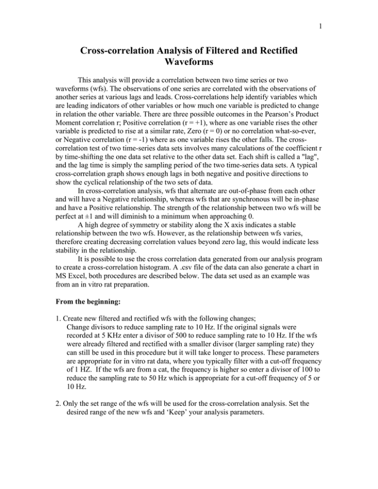
1 Cross-correlation Analysis of Filtered and Rectified Waveforms This analysis will provide a correlation between two time series or two waveforms (wfs). The observations of one series are correlated with the observations of another series at various lags and leads. Cross-correlations help identify variables which are leading indicators of other variables or how much one variable is predicted to change in relation the other variable. There are three possible outcomes in the Pearson’s Product Moment correlation r; Positive correlation (r = +1), where as one variable rises the other variable is predicted to rise at a similar rate, Zero (r = 0) or no correlation what-so-ever, or Negative correlation (r = -1) where as one variable rises the other falls. The crosscorrelation test of two time-series data sets involves many calculations of the coefficient r by time-shifting the one data set relative to the other data set. Each shift is called a "lag", and the lag time is simply the sampling period of the two time-series data sets. A typical cross-correlation graph shows enough lags in both negative and positive directions to show the cyclical relationship of the two sets of data. In cross-correlation analysis, wfs that alternate are out-of-phase from each other and will have a Negative relationship, whereas wfs that are synchronous will be in-phase and have a Positive relationship. The strength of the relationship between two wfs will be perfect at ±1 and will diminish to a minimum when approaching 0. A high degree of symmetry or stability along the X axis indicates a stable relationship between the two wfs. However, as the relationship between wfs varies, therefore creating decreasing correlation values beyond zero lag, this would indicate less stability in the relationship. It is possible to use the cross correlation data generated from our analysis program to create a cross-correlation histogram. A .csv file of the data can also generate a chart in MS Excel, both procedures are described below. The data set used as an example was from an in vitro rat preparation. From the beginning: 1. Create new filtered and rectified wfs with the following changes; Change divisors to reduce sampling rate to 10 Hz. If the original signals were recorded at 5 KHz enter a divisor of 500 to reduce sampling rate to 10 Hz. If the wfs were already filtered and rectified with a smaller divisor (larger sampling rate) they can still be used in this procedure but it will take longer to process. These parameters are appropriate for in vitro rat data, where you typically filter with a cut-off frequency of 1 HZ. If the wfs are from a cat, the frequency is higher so enter a divisor of 100 to reduce the sampling rate to 50 Hz which is appropriate for a cut-off frequency of 5 or 10 Hz. 2. Only the set range of the wfs will be used for the cross-correlation analysis. Set the desired range of the new wfs and ‘Keep’ your analysis parameters. 2 Filtered/rectified ENGs used in this analysis. 3. Create a plot file of the cross-correlation of two wfs, specifying the down-sampling frequency for the wfs, and the number of lags desired. At the command prompt, enter ‘getwfdata –f10 run-file-name wf# wf# | crosscorr –l150 – | genplot –yf– –yc2 –yr-1.0001,1.0001 –yg.2 –xr-150,150 –xo-151 –yw0 –yp2 \ –xhLag –yhCCF > crossw#-#.plt’ The –f10 option to getwfdata specifies a downsampling frequency of 10 Hz, which we find is adequate for ENGs that were rectified and low-pass filtered at 1 Hz. The –l (lower-case “L”) option to crosscorr specifies the number of time lags for the crosscorrelation analysis. 150 lags for data at 10 Hz will give you ±15 seconds of lag, which is enough to show periodicity over a few step cycles. The genplot command requires a myriad of options: –yf– –yc2 reads the Y-axis data from column 2 of the pipe (the crosscorr output), –yr specifies the Y-axis range (±1 with a tad extra to ensure the ticks show up at -1 and +1 on the graph), –yg specifies the Y-axis tick gap, –xr specifies the X-axis range (±150 lags) and –xo specifies the offset for this axis to get the first data point at the right X coordinate on the graph (from 1 to -150), –yw0 specifies a line graph, –yp2 uses pen 2 (blue) for drawing the data series, and –xh and –yh specify the X- and Y-axis labels. The output of genplot is redirected to an HPGL plot file. Again, these parameters are appropriate for in vitro rat data; for cat data, down 3 sample to 50 Hz and use 200 – 300 lags. 50 Hz with 200 lags is 4 sec (approximately 4 cycles) of data for comparison. 4. Ftp this plot file to windows computer if you need to make a final graph in CorelDraw. 5. If you want to combine two cross-correlations on the same graph, you can easily repeat the command above with a few different options to select different wfs and different pen colours. Select the appropriate wf# arguments to getwfdata for the second crosscorrelation, change the –yp2 option to genplot to –yp4 –xp0, to use pen 4 (red) for the second data series and pen 0 (turn off drawing) for the axes, and use a double-redirect symbol “>>” to add the second graph to the same plot file as the first graph. E.g.: getwfdata –f10 apjedro4damp02 5 6 | crosscorr –l150 – | genplot –yf– –yc2 –yr-1.0001,1.0001 –yg.2 –xr-150,150 –xo-151 \ –yw0 –yp2 –xhLag –yhCCF > ccfrl5ll2rl2.plt getwfdata –f10 apjedro4damp02 5 4 | crosscorr –l150 – | genplot –yf– –yc2 –yr-1.0001,1.0001 –yg.2 –xr-150,150 –xo-151 \ –yw0 –yp4 –xp0 >> ccfrl5ll2rl2.plt In this example, wf 5 is the rectified/filtered RL5 ENG, wf 6 is LL2 and wf 4 is RL2, so the graph will show cross-correlations of RL5 with LL2 in blue, and RL5 with RL2 in red. Cross-correlations of RL5 with LL2 in blue, and RL5 with RL2 in red. The RL5/LL2 curve will show left-right alternation. This indicates that the two are in phase as shown by a high positive CCF at lag 0. The RL5/RL2 curve will show flexor/extensor alternation on the right side indicating that the two are out of phase as shown by a high negative CCF at lag 0. 4 Creating a cross-correlation histogram figure using MS Excel 1. Create a .csv file of the cross-correlation of two wfs, specifying the down-sampling frequency for the wfs, and the number of lags desired. At the command prompt, enter ‘getwfdata –f10 run-file-name wf# wf# | crosscorr –l150 – > crossw#-#.csv’ 2. Ftp this file to windows computer. Open it in Excel. 3. Repeat the steps above for a second cross-correlation of two other wfs, if you want to combine them into one graph, then select the second column from the second .csv file, copy and paste into the third column of the first .csv file. 4. Save as an Excel spreadsheet (.xls file) so that the chart will be saved later. 3. Select all columns then select the Chart Wizard. Select ‘XY (Scatter)’ then select ‘Scatter with data points connected by smoothed lines without numbers’. Then select ‘Next’ and ‘Finish’. You now have a chart that can be edited in CorelDraw for the final figure. 1 0.8 0.6 0.4 CCF 0.2 RL5 with LL2 0 -150 -100 -50 -0.2 0 50 100 150 -0.4 -0.6 -0.8 -1 Lag Cross-correlation histogram figure using MS Excel RL5 with RL2 5 References: Madriaga MA, McPhee LC, Chersa T, Christie KJ, Whelan PJ. (2004) Modulation of locomotor activity by multiple 5-HT and dopaminergic receptor subtypes in the neonatal mouse spinal cord. J Neurophysiol, 92(3),1566-76 Pearlstein E, Mabrouk FB, Pflieger JF, Vinay L. (2005) Serotonin refines the locomotorrelated alternations in the in vitro neonatal rat spinal cord. Eur J Neurosci, 21(5),1338-46 Kremer, E., & Lev-Tov, A. (1997). Localization of the spinal network associated with generation of hindlimb locomotion in the neonatal rat and organization of its transverse coupling system. Journal of Neurophysiology, 77(3), 1155-1170. Paul Bourke, Cross Correlation, 1996, http://astronomy.swin.edu.au/~pbourke/other/correlate/ Jenný Brynjarsdóttir, Sigrún Helga Lund, Kjartan G. Magnússon and Ólafur K. Nielsen, Analysis of time series for rock ptarmigan and gyrfalcon populations, http://www.raunvis.hi.is/~kgm/Papers/RH-18-2003.pdf This last reference suggested converting each data series to white noise series by filtering the data series by subtracting estimates generated by a proprietary modeling program then calculating the residuals. This procedure would reduce the variability of their sample due to very low N’s (n=4-5). This procedure is not necessary in our application as our N’s are of sufficient size to reduce variability in our sample to a negligible amount.
