Measurement and Control of Microphonics in High Loaded-Q
advertisement

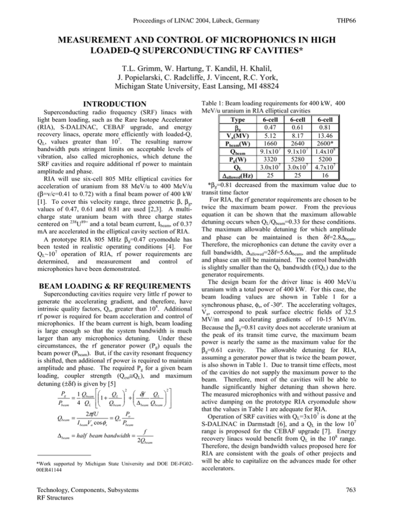
Proceedings of LINAC 2004, Lübeck, Germany THP66 MEASUREMENT AND CONTROL OF MICROPHONICS IN HIGH LOADED-Q SUPERCONDUCTING RF CAVITIES* T.L. Grimm, W. Hartung, T. Kandil, H. Khalil, J. Popielarski, C. Radcliffe, J. Vincent, R.C. York, Michigan State University, East Lansing, MI 48824 INTRODUCTION Superconducting radio frequency (SRF) linacs with light beam loading, such as the Rare Isotope Accelerator (RIA), S-DALINAC, CEBAF upgrade, and energy recovery linacs, operate more efficiently with loaded-Q, QL, values greater than 107. The resulting narrow bandwidth puts stringent limits on acceptable levels of vibration, also called microphonics, which detune the SRF cavities and require additional rf power to maintain amplitude and phase. RIA will use six-cell 805 MHz elliptical cavities for acceleration of uranium from 88 MeV/u to 400 MeV/u (β=v/c=0.41 to 0.72) with a final beam power of 400 kW [1]. To cover this velocity range, three geometric β, βg, values of 0.47, 0.61 and 0.81 are used [2,3]. A multicharge state uranium beam with three charge states centered on 238U89+ and a total beam current, Ibeam, of 0.37 mA are accelerated in the elliptical cavity section of RIA. A prototype RIA 805 MHz βg=0.47 cryomodule has been tested in realistic operating conditions [4]. For QL~107 operation of RIA, rf power requirements are determined, and measurement and control of microphonics have been demonstrated. BEAM LOADING & RF REQUIREMENTS Superconducting cavities require very little rf power to generate the accelerating gradient, and therefore, have intrinsic quality factors, Qo, greater than 108. Additional rf power is required for beam acceleration and control of microphonics. If the beam current is high, beam loading is large enough so that the system bandwidth is much larger than any microphonics detuning. Under these circumstances, the rf generator power (Pg) equals the beam power (Pbeam). But, if the cavity resonant frequency is shifted, then additional rf power is required to maintain amplitude and phase. The required Pg for a given beam loading, coupler strength (Qext≅QL), and maximum detuning (±δf) is given by [5] Pg Pbeam Qbeam 2 2 1 Qbeam QL δf QL 1+ = + 4 QL Qbeam ∆ beam Qbeam 2πfU Po = = Qo I beamVa cos φs Pbeam ∆ beam = half beam bandwidth = f 2Qbeam *Work supported by Michigan State University and DOE DE-FG0200ER41144 Technology, Components, Subsystems RF Structures Table 1: Beam loading requirements for 400 kW, 400 MeV/u uranium in RIA elliptical cavities Type 6-cell 6-cell 6-cell 0.47 0.61 0.81 βg 5.12 8.17 13.46 Va(MV) 1660 2640 2600* Pbeam(W) 9.1x10⁷ 9.1x10⁷ 1.4x10⁸ Qbeam 3320 5280 5200 Pg(W) 3.0x10⁷ 3.0x10⁷ 4.7x10⁷ QL 25 25 16 ∆allowed(Hz) *βg=0.81 decreased from the maximum value due to transit time factor For RIA, the rf generator requirements are chosen to be twice the maximum beam power. From the previous equation it can be shown that the maximum allowable detuning occurs when QL/Qbeam=0.33 for these conditions. The maximum allowable detuning for which amplitude and phase can be maintained is then δf=2.8∆beam. Therefore, the microphonics can detune the cavity over a full bandwidth, ∆allowed=2δf=5.6∆beam, and the amplitude and phase can still be maintained. The control bandwidth is slightly smaller than the QL bandwidth (f/QL) due to the generator requirements. The design beam for the driver linac is 400 MeV/u uranium with a total power of 400 kW. For this case, the beam loading values are shown in Table 1 for a synchronous phase, φs, of -30º. The accelerating voltages, Va, correspond to peak surface electric fields of 32.5 MV/m and accelerating gradients of 10-15 MV/m. Because the βg=0.81 cavity does not accelerate uranium at the peak of its transit time curve, the maximum beam power is nearly the same as the maximum value for the The allowable detuning for RIA, βg=0.61 cavity. assuming a generator power that is twice the beam power, is also shown in Table 1. Due to transit time effects, most of the cavities do not supply the maximum power to the beam. Therefore, most of the cavities will be able to handle significantly higher detuning than shown here. The measured microphonics with and without passive and active damping on the prototype RIA cryomodule show that the values in Table 1 are adequate for RIA. Operation of SRF cavities with QL=3x10⁷ is done at the S-DALINAC in Darmstadt [6], and a QL in the low 107 range is proposed for the CEBAF upgrade [7]. Energy recovery linacs would benefit from QL in the 108 range. Therefore, the design bandwidth values proposed here for RIA are consistent with the goals of other projects and will be able to capitalize on the advances made for other accelerators. 763 THP66 Proceedings of LINAC 2004, Lübeck, Germany Finally, Lorentz detuning which is a shift in the cavity frequency due to radiation pressure of the electromagnetic field must be compensated for during rf turn on. For RIA, a cw linac, this can be done slowly using the tuner and will not be a critical issue. METHODS OF MITIGATION Vibrations and pressure fluctuations cause the cavity frequency to shift (detune) only if the forces distort the cavity walls. Typical sources of vibration are rotating machinery, fluid fluctuations, and ground motion. Motors will generate discrete vibration frequencies at harmonics of their revolution rate. Fluid fluctuations such as boiling, cavitation, and turbulent flow, and ground motion will generate a broadband vibration spectrum. There are many techniques to reduce microphonics or otherwise mitigate their effect on an SRF cavity. The mechanical frequencies of concern are usually low (less than 200 Hz). A proper cavity and cryomodule design can significantly reduce the microphonics problem. The cavity can be made more rigid with thicker material and gussets to reduce distortions, but the tuner will become more complicated and heat transfer from the rf surface to the helium bath may be degraded. Structural resonances should be eliminated or shifted to higher frequency. As an example, the lowest frequency transverse mechanical mode of the 805 MHz cavities was removed with a support at the center of the six-cell structure. Designing the cavity and helium vessel so that distortions in regions of high electric field are canceled by distortions in high magnetic field regions can reduce the frequency shift due to pressure fluctuations in the helium bath. Passive mechanical dampers can be integrated into the cavity as has become standard for quarter-wave resonators [8]. The choice of operating temperature can have a large influence on microphonics excitation. Operation at 4 K results in helium at atmospheric pressure with fluctuations from the plant and pool boiling heat transfer with its concomitant broadband vibration. Operation at 2 K has sub-atmospheric liquid helium with lower disturbances from the cryoplant, and heat transfer via conduction is enhanced due to the unique properties of superfluid. Another system design issue is cw versus pulsed operation. Pulsed operation must deal with the transient Lorentz force detuning, which is likely to dominate all other microphonic sources. Sources of vibration should be eliminated when possible or isolated from the cryomodule. Vibrations will be transmitted through the ground, pipes and fluids. Passive and active absorbers can reduce the amplitude before the vibrations reach the cryomodule and cavity. Examples from other disciplines are optical benches, telescopes, automobile suspension systems, and sound cancellation [9]. Vibrations that reach the cryomodule can be actively and passively damped before that motion affects the cavity. Even with the damping and isolation techniques listed above, there will likely still be some cavity vibration. There are several methods available to compensate the 764 microphonics. A fast mechanical tuner can distort the cavity shape and cancel the frequency shift induced by the microphonics. Another way to apply a force on the cavity is to vary the accelerating gradient by a small but acceptable amount and use the Lorentz force [10]. The cavity frequency can also be shifted using a tunable reactive element that is coupled through the input power coupler or a dedicated fast tuner coupler [11,12]. Finally, small changes in the synchronous phase can accommodate the microphonics by allowing the rf drive frequency to remain on resonance, as is done with the VCX tuner [12], with an additional correction to the voltage amplitude given the known phase error. MEASUREMENTS The prototype RIA 805 MHz βg=0.47 cryomodule has two multi-cell cavities with fixed input power couplers and external tuners actuated by a room temperature piezoelectric actuator [4]. The cavities are cooled by 2 K superfluid with cryoplant temperature regulation. The coupler strength, Qext, is varied from 6x10⁴ to 6x10⁹ using an external transmission line transformer. Figure 1 shows a cross section of the cavity with tuner and coupler. Real-time frequency detuning measurements were made for modulation rates from dc to greater than 1 kHz. Figure 2 shows the microphonics measurement technique. A stable signal generator in open loop mode is used to drive the rf cavity, and a pickup from the cavity is mixed with the input to generate an error signal that is proportional to the cavity detuning. Since QL is adjustable, the system bandwidth is set so the peak detuning is within the system bandwidth and generates linear error signals. This technique gives real-time error signals that can be analyzed or used for feedback/feedforward. Other methods give similar results, but require a longer acquisition time, more stable signal generator, and cannot be used for feedback [13]. Figure 1: Side view of cavity with room temperature tuner and fixed input coupler. Technology, Components, Subsystems RF Structures Proceedings of LINAC 2004, Lübeck, Germany At 2 K low power measurements were made with the liquid helium partially filling the distribution pipe as would be done for operation. The maximum frequency deviation using the calibrated error signal was less than 40 Hz peak-to-peak (see figure 2). The error signal was calibrated using a known frequency shift from the signal generator. The measured modulation spectrum was primarily comprised of discrete Fourier components with modulation frequencies less than 80 Hz. The main components were at 59.5 and 59.7 Hz. They could be clearly distinguished from 60 Hz electronic pickup, which was negligible in these measurements. Additional components near 54 Hz, which is the lowest frequency natural mode of the cavity, were measured and likely due to other nearby motors. Using an accelerometer, the primary sources of vibration were identified to be the two cryoplant screw compressors (rated for 1500 hp/3560 rpm and 250 hp/3550 rpm). The cryoplant was designed to cool superconducting magnets so vibration was not a consideration, and no isolation from the floor or the piping was implemented. The motors are about 20 m from the cryomodule test area. For RIA the cryoplant motors will be farther away and better isolated. 20 3180704-001 40 60 no damping damping 0 Peak-to-peak Cavity Detune (Hz) 80 Figure 2: Microphonics measurement and control technique. 30 40 50 60 70 80 Disturbance Frequency (Hz) Figure 3: Fourier components of cavity detuning with and without active damping. Technology, Components, Subsystems RF Structures THP66 Since the detuning spectrum is made up primarily of discrete sinusoidal disturbances, an adaptive feedforward scheme was used to damp individual Fourier components [14]. The dominant microphonics signal was determined to consist of two closely spaced sinusoidal disturbances whose damping would be more problematic then a single peak, so for demonstration purposes a small motor with a Fourier component at about 57 Hz was placed on the cryomodule to generate a known sinusoidal disturbance. Figure 3 shows the Fourier components before and after active compensation and shows about a factor of seven damping of the 57 Hz component. The measured microphonics are near required levels for RIA without active damping, and can be brought below them using the adaptive feedforward cancellation. REFERENCES [1] C.W. Leemann, “The Rare-Isotope Accelerator (RIA) Facility Project,” in Proceedings of the XX International Linac Conference, Monterey, California (2000). [2] G. Ciovati et al., “Superconducting Prototype Cavities for the Spallation Neutron Source (SNS) Project,” in Proc. of the 2001 PAC, Chicago (2001). [3] W. Hartung et al.,“Status Report on Multi-Cell Superconducting Cavity Development for MediumVelocity Beams,” in Proceedings of the 2003 Particle Accelerator Conference, Portland, Oregon (2003). [4] T.L. Grimm et al., “Experimental Study of an 805 MHz Cryomodule for the Rare Isotope Accelerator”, these proceedings. [5] H. Padamsee et al., “RF superconductivity for Accelerators”, John Wiley & Sons, p. 391 (1998). [6] H.-D. Gräf, “Experience with Control of Frequency, Amplitude and Phase”, in Proc. of the 5th Workshop on RF Superconductivity, Hamburg, Germany (1992). [7] L. Harwood, “Upgrading CEBAF to 12 GeV,” in Proc. of the 2003 PAC, Portland, Oregon (2003). [8] A. Facco, “Mechanical Mode Damping in Superconducting Low-β Resonators, Particle Accelerators, vol. 61, pp. 265-278 (1998). [9] A. Hull, C. Radcliffe, S.C. Southward, “Global Active Noise Control of a One Dimensional Acoustic Duct Using a Feedback Controller”, ASME J. Dynamic Systems, Measurement and Control, Vol. 115, pp.488-494 (1993). [10] J.R. Delayen, “Electronic Damping of Microphonics in Superconducting Cavities”, in Proceedings of the 2001 Particle Accelerator Conference, Chicago (2001). [11] A.K. Mitra et al., “Coarse and fine tuners for the CERN PS 40 MHz Buncher Cavity”, in Proc. of the 1997 Particle Accelerator Conference, Vancouver (1997). [12] R. Pardo et al., “Long-Term Operating Experience for the ATLAS Superconducting Resonators,” in 9th Workshop on RF Superconductivity, Santa Fe, (1999). [13] M.P. Kelly et al., “Microphonics Measurements in SRF Cavities for RIA”, in Proceedings of the 2003 Particle Accelerator Conference, Portland (2003). [14] T. Kandil et al., “Adaptive Feedforward Cancellation of Sinusoidal Disturbances in Superconducting RF Cavities”, these proceedings. 765


