Copeland Scroll™ ZSI Compressor
advertisement
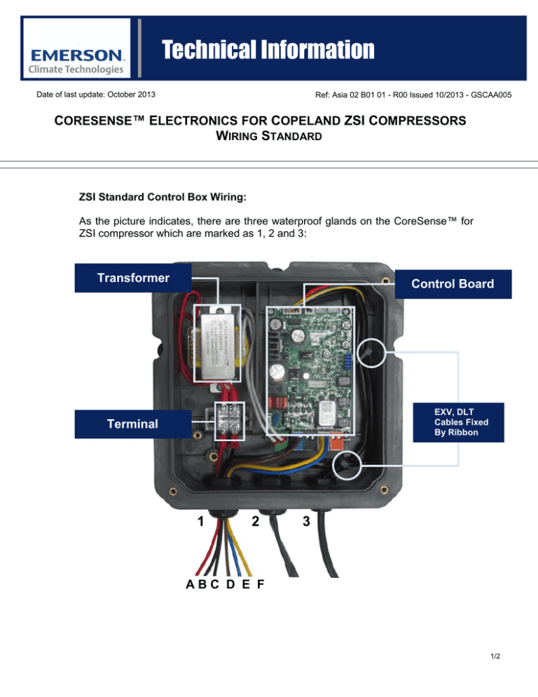
Technical Information Date of last update: October 2013 Ref: Asia 02 B01 01 - R00 Issued 10/2013 - GSCAA005 CORESENSE™ ELECTRONICS FOR COPELAND ZSI COMPRESSORS WIRING STANDARD ZSI Standard Control Box Wiring: As the picture indicates, there are three waterproof glands on the CoreSense™ for ZSI compressor which are marked as 1, 2 and 3: Transformer Control Board EXV, DLT Cables Fixed By Ribbon Terminal 1 2 3 ABC D E F 1/2 Technical Information Date of last update: June 2013 Waterproof Gland No. Ref: Asia 02 B01 01 - R00 Issued 6/2013 - GSCAA005 Gland 1 Gland 2 Gland 3 EXV Coil DLT Sensor A (Red) and B (Black): Controller Power Supply Input (220 – 240 VAC 50/60 Hz) Wire Function C (Black) and D (Brown): Compressor Start/Stop Input (220 – 240 VAC 50/60 Hz) E (Blue) and F (Yellow): Compressor Contactor Coil Control Output Wires A and B: Connect to terminal Wire Connection Wires C and D: Connect to the blue connector on the control board Connect to the Connect to the EXV port at the top DLT port at the top edge of the control edge of the control board board Wires E and F: Connect to the gray connector on the control board Gland Interal Diameter Range 2 – 3 mm Internal wire size: 18 AWG Rated voltage: 300V/600V Jacket Line Requirement Rated temperature: 80/105 ℃ Recommended: UL105, UL1011,UL1007 2/2

