Document
advertisement
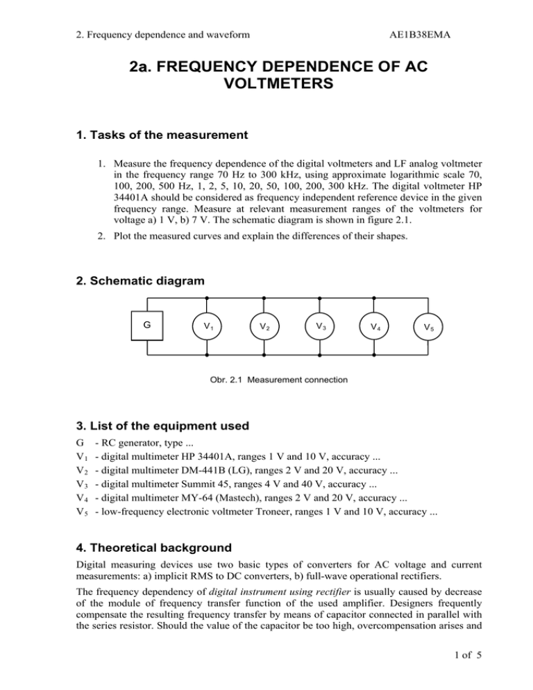
2. Frequency dependence and waveform AE1B38EMA 2a. FREQUENCY DEPENDENCE OF AC VOLTMETERS 1. Tasks of the measurement 1. Measure the frequency dependence of the digital voltmeters and LF analog voltmeter in the frequency range 70 Hz to 300 kHz, using approximate logarithmic scale 70, 100, 200, 500 Hz, 1, 2, 5, 10, 20, 50, 100, 200, 300 kHz. The digital voltmeter HP 34401A should be considered as frequency independent reference device in the given frequency range. Measure at relevant measurement ranges of the voltmeters for voltage a) 1 V, b) 7 V. The schematic diagram is shown in figure 2.1. 2. Plot the measured curves and explain the differences of their shapes. 2. Schematic diagram G V1 V2 V3 V4 V5 Obr. 2.1 Measurement connection 3. List of the equipment used G V1 V2 V3 V4 V5 - RC generator, type ... - digital multimeter HP 34401A, ranges 1 V and 10 V, accuracy ... - digital multimeter DM-441B (LG), ranges 2 V and 20 V, accuracy ... - digital multimeter Summit 45, ranges 4 V and 40 V, accuracy ... - digital multimeter MY-64 (Mastech), ranges 2 V and 20 V, accuracy ... - low-frequency electronic voltmeter Troneer, ranges 1 V and 10 V, accuracy ... 4. Theoretical background Digital measuring devices use two basic types of converters for AC voltage and current measurements: a) implicit RMS to DC converters, b) full-wave operational rectifiers. The frequency dependency of digital instrument using rectifier is usually caused by decrease of the module of frequency transfer function of the used amplifier. Designers frequently compensate the resulting frequency transfer by means of capacitor connected in parallel with the series resistor. Should the value of the capacitor be too high, overcompensation arises and 1 of 5 2. Frequency dependence and waveform AE1B38EMA the measured value is higher that it should be (for even higher frequency the value decrease caused by before-mentioned effects follows). Similar effects may be caused by parasitic capacitance of high-value series resistors. Frequency range of the digital devices with implicit RMS to DC value converter is usually higher - hundreds of kHz - and it is usually given by parameters of the used converter and by frequency response of the amplifiers. Integrated circuit AD 637 (more accurate devices) or AD 636 are used in most devices. Measurement Hints The generator output amplitude must be set in a way that the reference voltmeter shows a) 1V, b) 10V for 70Hz (the frequency is chosen to be different from power supply frequency 50Hz since the power supply interference may caused unstable device reading). The readings of all other connected voltmeters must be checked at the frequency 70 Hz as well, verifying that they fit into tolerance range (the difference between checked and reference voltmeters should not exceed the sum of absolute tolerance values of both devices). Digital voltmeter HP 34401A is the most accurate device of all voltmeters used in this task in the given frequency range up to 300 kHz according to its specifications. Therefore, it will be used as the reference device at all frequencies both for 1 V and 10 V. All remaining device readings must be acquired for given frequencies. The dependencies fn f n ( f ) shall be plotted into the graph. α fn means reading of the device V n at frequency f. Logarithmic scale should be used for x axe (frequency). The limit frequency at which the device accuracy does not fulfil its specifications can be obtained from table or from graphs. 2 of 5

