The Orsay 200-MeV Synchro-Cyclotron
advertisement

Proceedings of the 7th International Conference on Cyclotrons and their Applications, Zürich, Switzerland
THE ORSAY 200 MeV SYNCHROCYCLOTRON
A. Laisne, Institut de Physique Nucleaire, 91406 - Orsay, France
Present status of the 200 MeV synchrocyclotron machine
I - Main Features :
The proposal for the 157 MeV p. Orsay synchrocyclotron modification was accepted on december 1972 and the project, which consists in rebuilding of a new multiparticle synchrocyclotron 200
MeV p. keeping the existing yoke (with some additional 200 tons of magnetic iron) and rearranging
all the beam handling system in order to turn the
heavy experimental apparatus to the best account,
was presented at the 10th and 11th ECPM
(Groningen 1973 and Louvain-la-Neuve, june 1974).
for the machine itself, the continuation of theses
for the new beam handling systems, the manufacturing and testing of all theses new elements and
the beginning of the re - installation of the understructure after a three month period of dismantling
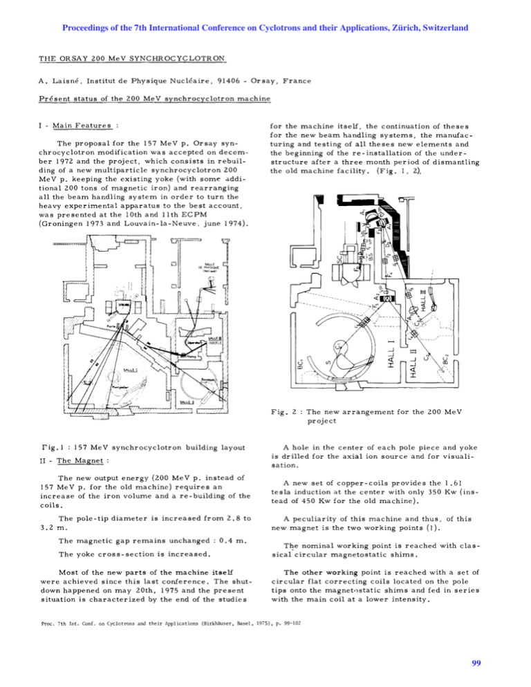
the old machine facility. (Fig. 1, 2).
~'"''
J
o
DE PHYSIQUE
IhoIISl/d)
,
,{J
....
lC~~~ ____ _
'
Fig. 2
rig. 1 : 157 MeV synchrocyclotron building layout
II - The Magnet :
The new arrangement for the 200 MeV
project
A hole in the center of each pole piece and yoke
is drilled for the axial ion source and for visualisation.
The new output energy (200 MeV p. instead of
157 MeV p. for the old machine) requires an
increase of the iron volume and a re - building of the
coils.
A new set of copper-coils provides the 1.61
tesla induction at the center with only 350 Kw (instead of 450 Kw for the old machine).
The pole-tip diameter is increased from 2.8 to
3.2 m.
A peculiarity of this machine and thus, of this
new magnet is the two wor king points (1).
The magnetic gap remains unchanged
0.4 m.
The yoke cross-section is increased.
Most of the new parts of the machine itself
were achieved since this last conference. The shutdown happened on may 20th, 1975 and the present
situation is characterized by the end of the studies
T~e nominal working point is reached with classical circular magneto static shims.
The other working point is reached with a set of
circular flat correcting coils located on the pole
tips onto the magnet.)static shims and fed in series
with the main coil at a lower intensity.
Proc. 7th Int. Con£. on Cyclotrons and their Applications (Birkhauser, Basel, 1975), p. 99-102
99
Proceedings of the 7th International Conference on Cyclotrons and their Applications, Zürich, Switzerland
So the following ene rgies would then be reached.
E
p
E3
E
He
++
ex
Ed
200 MeV
and
170 MeV
282.7 MeV
and
238 MeV
217.4 MeV
and
182.4 MeV
108 MeV
and
90.6 MeV
We took over the following newly :manufactured parts,
the c opper coils
(fig. 4)
the vacuu:m cha:mber
(fig. 5)
two additional pieces of iron for the return
yoke.
Fig.4. Arrival of half the new copper- coils
The new pole tips and other pieces of iron for
the yoke are being :machined.
The dr illing :machine for the hole in the lower
part of the yoke was borrowed fro:m the Cern SC
and will soon be put in operation.
The set of "kapton" insulated copper correcting coils is under fabrication.
III - The R. F. Syste:m.
III. 1. Parts located in the vacuu:m cha:mber
We have chosen a D-du:m:my D structure which
is strictly sy:m:metrical with respect to the line
axis with a 60 :m:m vertical aperture. This rigid set
is allowed to rotate in the horizontal plane with in
circle 6 :m:m in radius. It a lso carries all the central geo:metry, including the axial ion source, in
order to obtain the be st orbit cent er ing.
Fig. 5. Manufacturing the vacuu:m cha:mber
All these R.F parts are ready and the t e sts
for transverse :modes we re achieved (2). Thus a
central and two lateral slots we re :made to shift the
first transverse :mode fro:m 60 MHz to 50 MHz
where the bea:ms cannot excite it. The second :mode
can only be excited by a fifth har:monic of the protons bea:ms (fig. 6).
III. 2. The line.
n.
The
/2 coaxial line which is at at:mospheric
pressure is di:mensionned according to the highest
R.F frequency (3).
The require:ment for the second working point
leads to 3 new frequency ranges added to the three
ranges necessary for the no:mina l energy.
Thus a single ape rture is :made on the internal
conductor of the line which puts in series a variable
inductance by the :means of a :moving short in
another 68 oh:ms internal coaxial line. Fig. 7 and 8.
Fig. 6. The "D' -du:m:my D" :movable structure
100
Proceedings of the 7th International Conference on Cyclotrons and their Applications, Zürich, Switzerland
Two 1000 pF variable capacitors located on the
line at the voltage node for the highe st frequency
allow the enlargement of the frequency range obtained with the two existing rotating condensers of the
old machine.
80 % of these two concentric coaxial lines
placed at atmospheric pressure are made. The left
20 % consist in "model" elements which will allow
to give four different length and therefore, four
measurement points to adjust the dimensions
(fig. 9).
III. 3. Oscillator.
The "Colpitts type" oscillator is a 4 CW 2500A
Eimac tube providing the 14000 to 20000 "D" voltage. This oscillator in its cabinet is r eady.
II1.4 . The new rotating condenser will have
the same t, -Cas the - oid- pre se~t -o"i.e-s-. It will deliver, at a frequency between 700 and 1200 Hz a
sawtooth modulation permitting an acceleration
duty cycle of about 70 a 75
The maximum peak
voltage between blades will De 33 KV for 20 KV
peak on the "D". This new rotating condenser is
being studied.
%.
Fig. 7. Side view
----- -------
IV - The ion source.
The study of the device introducing th e ion
sourc e (classical hooded arc ion source) into the
machine is finished and we started working it out
(fig. 7).
V - The extraction system.
V.I. The electromagnetic channel (4), with
its 3 mm thick~ater---c-o-o-led-copper-septum (fig .
10), and the iron-free coil surr ounding it (fig. 11)
are ready. The set is being put in place for magnetic field measurements.
Fig. 8. Top view
This electromagnetic channel gives, with a
focusing gradient of 200 G / cm in the horizontal
plane a 60 cm long, 0.25 T average field drop off
in order to jump over the iron septum of the following magnetostatic element.
The DC power supply 10 KV 4 A is followed
by an amplitude modulator TBW 12-100 vacuum
tube which is being tested.
V. 2.
channel.
!"?.:":.':r:. _s~pp~y _f_o:_ !I:': :~~:!r_~~~~.?_e~~c:
We are presently testing the 200 Kw , 7500 A
D.C transistor ballast power supply (fig. 12).
V. 3. '!'~~ _~_a~_n_e:9~!~t!: _c:I:~~~,:I_s_.
A 24/40 th scale model of the main elements
of the magne to static channel was made and tested
in a magnet , parralel to wrinting computer codes
(4).
Fig.9. The air-pressure line. On the left,
the hole for the 1000 pF jennings
variable capacitors.
101
Proceedings of the 7th International Conference on Cyclotrons and their Applications, Zürich, Switzerland
Fig. 10. Electromagnetic channel septum
Th e g eo m e trical siz e s of thes e elements are
determined and b e ing studied (fig. 8). Th e set has
to b e achieved and put in place in the machine by
the end of 1975.
Fig. 11. Iron-free coil a nd septum support
VI - Vacuum syste m.
W e will keep th e pumping system of the old
machine.
Fig. 12. Electromagnetic channel power supply
IPN internal reports:
(I) NTTS n° 22
sept. 1973
(2) NTTS n° 33
mars 1974
A. Lafoux, A. Laisne : Etude
d'un point de fonctionnement it
energie infer ieure it I' energie
nomina Ie .
A. Laisne
Modes transverses.
NTTS nO 56
juin 1975
A. Laisne : Mesures effectuees
sur Ie "D". Modes transvers e s.
(3) NTTS n° 47
d ec . 1974
A. Laisne : dimensionnement de
la structure HF dans sa version
semi definitive.
102
(4) NTTS nO 7
mars 1973
A. Lafoux, E. Martin : Premiers
resultats sur l'etude theorique de
l'extraction du faisceau.
NTTS n° 45
octobre 1974
E. Martin : Le point sur Ie canal
e lectromagne tique. Le projet des
essais hors site.
NTTS nO 62
1974-1975
P. Janots , E. Martin : MINCO
un programme Fortran qui optimise la position transversale des
conducteur s du canal d' extraction
e lectromagnetique et Ie courant
qui les parcoure.
NTTS n ° 63
1974-1975
P. Janots , E. Martin: MINCO
Resultats confirmant la configuration du canal electromagnetique
choisi.


