Array Antenna for DVB-S Applications
advertisement
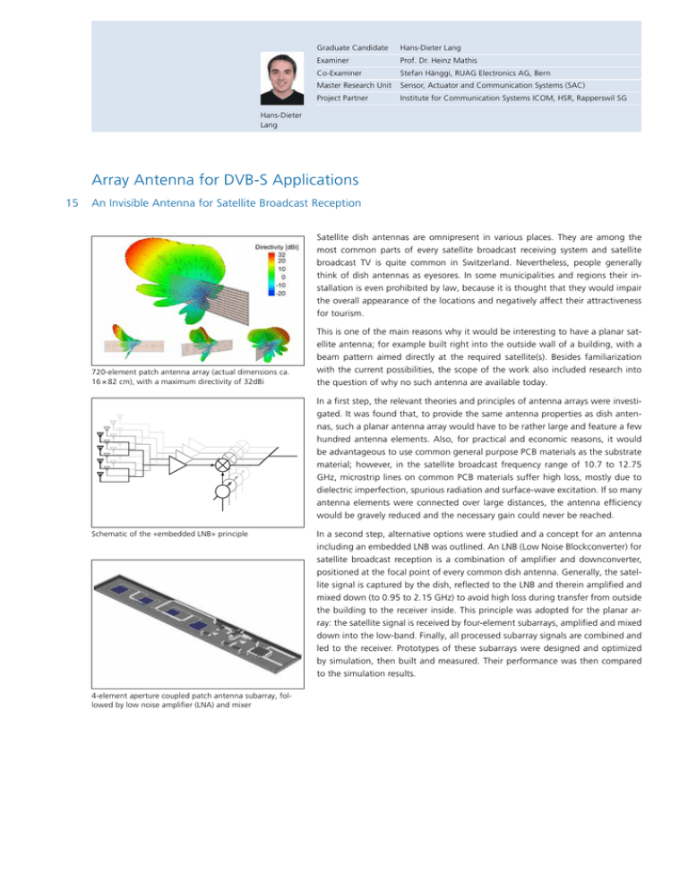
Graduate Candidate Hans-Dieter Lang Examiner Prof. Dr. Heinz Mathis Co-Examiner Stefan Hänggi, RUAG Electronics AG, Bern Master Research Unit Sensor, Actuator and Communication Systems (SAC) Project Partner Institute for Communication Systems ICOM, HSR, Rapperswil SG Hans-Dieter Lang Array Antenna for DVB-S Applications 15 An Invisible Antenna for Satellite Broadcast Reception Satellite dish antennas are omnipresent in various places. They are among the most common parts of every satellite broadcast receiving system and satellite broadcast TV is quite common in Switzerland. Nevertheless, people generally Array Feeding think of dish antennas as eyesores. In some municipalities and regions their installation is even prohibited by law, because it is thought that they would impair "Embedded Mixing" the overall appearance of the locations and negatively affect their attractiveness As discussed, a crucial point for large arrays is loss of the feeding structure, duefor tourism. ay Design oard LNB to lossy microstrip and spurious radiation. This point is even more crucial for antennas for satellite broadcast, since at those frequency range microstrip linesThis are several factors more lossy than for normal S- and L-band applications. is one of the main reasons why it would be interesting to have a planar satellite antenna; for example built right into the outside wall of a building, with a Therefore, to lower the loss in the feeding structure(s), it would be very effective beam pattern aimed directly at the required satellite(s). Besides familiarization to lower the frequency of the feeding structure. To achieve this, the LNB could already be realized inside the antenna, signal of a certainca. amount ofwith the current possibilities, the scope of the work also included research into 720-element patch antenna where array the (actual dimensions antennas in small subarrays could be gathered and mixed down to the frequencies 16 × 82 cm), with a maximum directivity of 32dBi for the satellite receiver. To accound for the conversion loss of the mixer (aboutthe question of why no such antenna are available today. 5 − 8 dB for these frequency ranges), an LNA has to be prefixed. Fig. 3.5 shows the overall schematic of several such subarrays. In Subarray 1. Feeder Preamplifier Mixer / Phaser 2. Feeder a first step, the relevant theories and principles of antenna arrays were investigated. It was found that, to provide the same antenna properties as dish antennas, such a planar antenna array would have to be rather large and feature a few hundred antenna elements. Also, for practical and economic reasons, it would be advantageous to use common general purpose PCB materials as the substrate material; however, in the satellite broadcast frequency range of 10.7 to 12.75 GHz, microstrip lines on common PCB materials suffer high loss, mostly due to dielectric imperfection, spurious radiation and surface-wave excitation. If so many antenna elements were connected over large distances, the antenna efficiency would be gravely reduced and the necessary gain could never be reached. In a second step, alternative options were studied and a concept for an antenna including an embedded LNB was outlined. An LNB (Low Noise Blockconverter) for The chosen mixer comes from MiniCircuits and is called SIM-24MH+. Its main satellite broadcast reception is a combination of amplifier and downconverter, features are shown in Tab. 3.4. positioned at the focal point of every common dish antenna. Generally, the satellite signal is captured by the dish, reflected to the LNB and therein amplified and MiniCircuits SIM-24MH+ Mixer mixed down (to 0.95 to 2.15 GHz) to avoid high loss during transfer from outside RF Bandwidth: 7.3 − 20 GHz the building to the receiver inside. This principle was adopted for the planar arIF Bandwidth: DC −7.5 GHz ray: the satellite signal is received by four-element subarrays, amplified and mixed Conversion Loss: 6.73 dB at 10 GHz, 5.93 at 11 GHz, 5.7 at 13 GHz LO-RF Isolation: 34 − 46 dB (from 10 − 12.5 GHz) down into the low-band. Finally, all processed subarray signals are combined and LO-IF Isolation: 16.8 − 18 dB (at 10 − 12.5 GHz) led to the receiver. Prototypes of these subarrays were designed and optimized IP3: 16 dB (at 10 − 14.5 GHz) by simulation, then built and measured. Their performance was then compared VSWR RF-Port: 2 − 3.3 (from 10 − 12.5 GHz) VSWR LO-Port: 2.3 − 3.5 (from 10 − 12.5 GHz) to the simulation results. Schematic «embedded LNB»ofprinciple Figure of 3.5theSchematic principle the array antenna Dimensions: low profile, area dimensions approx. 5 × 4.6 mm 4-element aperture coupled patch antenna subarray, folTable 3.4 Main features of the SIM-24HM+, from datasheet [82] lowed by low noise amplifier (LNA) and mixer 68
