a flexure balance with adjustable restoring torque for nano
advertisement

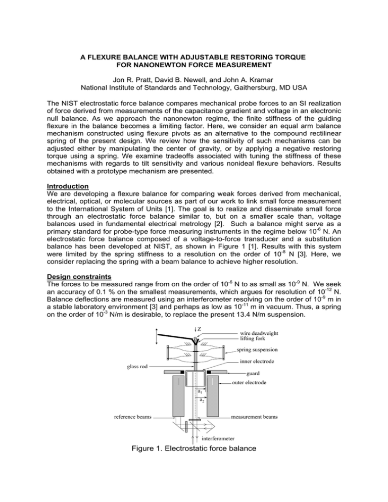
A FLEXURE BALANCE WITH ADJUSTABLE RESTORING TORQUE FOR NANONEWTON FORCE MEASUREMENT Jon R. Pratt, David B. Newell, and John A. Kramar National Institute of Standards and Technology, Gaithersburg, MD USA The NIST electrostatic force balance compares mechanical probe forces to an SI realization of force derived from measurements of the capacitance gradient and voltage in an electronic null balance. As we approach the nanonewton regime, the finite stiffness of the guiding flexure in the balance becomes a limiting factor. Here, we consider an equal arm balance mechanism constructed using flexure pivots as an alternative to the compound rectilinear spring of the present design. We review how the sensitivity of such mechanisms can be adjusted either by manipulating the center of gravity, or by applying a negative restoring torque using a spring. We examine tradeoffs associated with tuning the stiffness of these mechanisms with regards to tilt sensitivity and various nonideal flexure behaviors. Results obtained with a prototype mechanism are presented. Introduction We are developing a flexure balance for comparing weak forces derived from mechanical, electrical, optical, or molecular sources as part of our work to link small force measurement to the International System of Units [1]. The goal is to realize and disseminate small force through an electrostatic force balance similar to, but on a smaller scale than, voltage balances used in fundamental electrical metrology [2]. Such a balance might serve as a primary standard for probe-type force measuring instruments in the regime below 10-6 N. An electrostatic force balance composed of a voltage-to-force transducer and a substitution balance has been developed at NIST, as shown in Figure 1 [1]. Results with this system were limited by the spring stiffness to a resolution on the order of 10-8 N [3]. Here, we consider replacing the spring with a beam balance to achieve higher resolution. Design constraints The forces to be measured range from on the order of 10-6 N to as small as 10-9 N. We seek an accuracy of 0.1 % on the smallest measurements, which argues for resolution of 10-12 N. Balance deflections are measured using an interferometer resolving on the order of 10-9 m in a stable laboratory environment [3] and perhaps as low as 10-11 m in vacuum. Thus, a spring on the order of 10-3 N/m is desirable, to replace the present 13.4 N/m suspension. Z wire deadweight lifting fork spring suspension inner electrode glass rod guard outer electrode a1 a2 reference beams measurement beams interferometer Figure 1. Electrostatic force balance cross-strip flexure pivots at each joint Figure 2. Balanced parallelogram movement with cross-strip flexure pivots Alignment The inner cylinder translates through a range δ =± 500 µm. We seek to execute this motion without rotation, and parallel to gravity, using the parallelogram movement of Figure 2. The cosine error between the direction of gravity and electrostatic forces should contribute less than a few parts in 105 to the uncertainty of their comparison. A 100 mm lever arm satisfies this condition, giving a maximum angular deviation between the direction of motion and gravity of tan-1 δ/l ≈ 5 x 10⁻³ rad. Parasitic motion might cause the capacitance gradient to vary unacceptably. To investigate, we consider the capacitance per unit length for a pair of infinite right-cylindrical electrodes subject to a misalignment. According to Snow [4] dC = dz 1.11277 ⋅ 10 −7 where, 2bc = a12 + a 22 − b 2 + 2bc 2 log 2a1 a 2 ((a + a1 ) − b 2 2 2 ) ((a ) − a1 ) − b 2 , 2 2 (1) dC is the differential change in capacitance per differential length dz of the capacitor expressed in Farads per meter, a1 is the radius of the inner electrode, a2 the radius of the outer electrode, and b the radial distance that the center of the inner electrode is offset from the geometric center of the outer electrode. All dimensions are in meters. In our experiments, a1=7.5 mm and a2=7.95 mm. Substituting these numbers and letting b take values between 0 and 5 µm in Eq. (1), we obtain the results plotted in Figure 3. A 100 mm lever arm gives a 1.25 x 10⁻⁶ m offset through the range of travel, assuming ideal pivot behavior, and this yields an apparently negligible change in the predicted gradient. Figure 3. Capacitance gradient as a function of electrode offset Stiffness and sensitivity The mechanism is treated as a single beam that possesses a central pivot of torsional stiffness κ=Σ κi, where the κi are the torsional stiffness values associated with each pivot in the mechanism. For small rotations, the effective linear spring constant at the end of the beam is K=κ/l2, and the displacement sensitivity to a unit force applied at the end of the beam is simply 1/K. At first glance, it would appear that the desired sensitivity can be achieved simply by making a lever arm of sufficient length l. However, the cross-strip flexure pivots in our device have a nominal stiffness of 0.0013 N·m/rad [5]. A mechanism comprised of only one such pivot requires a lever arm over 1 m long to achieve our sensitivity goal. To reduce this length, we explore two mechanical compensation schemes that make use of negative restoring torques to reduce κ, the first using gravity, the second using a spring. x z l3 h m k κ l2 I γ l1 θ ϕ g Figure 4. Simplified balance schematic Gravity compensation The effective stiffness of a beam balance can be reduced by raising the center of gravity above the central pivot, provided one is willing to accept increased sensitivity to seismic perturbations [6]. Consider the simplified balance movement of Figure 4. For now, we ignore the linear spring k, so that the equation of motion for small angular displacements θ between the beam and horizontal is (I + mh )θ&& = −κ (θ − ϕ ) − cθ& + mghθ − mh&x& − mh&z&θ 2 where, ϕ is the tilt of the metrology frame, x is the motion of this frame parallel to the horizontal, z its motion in the direction of gravity, I is the mass moment of inertia of the beam about the central pivot, m is a point mass used to adjust the location of the beam center of gravity, h is the distance of this mass above the pivot, κ is the combined stiffness of the flexure pivots, and c is the viscous damping due to air. As reported in the literature [6,7], when the equilibrium angle θο =0, the axis of rotation and the center of mass are aligned in a direction parallel to gravity, and vibrations in the vertical direction can only excite the balance parametrically. However, a misalignment of these axes creates an error torque – mh&z&θ o directly coupled to accelerations in z [7]. We will assume the system is properly aligned, let γ=θ−ϕ , and write the equation of motion as (I + mh )γ&& + cγ& + (κ − mgh )γ = mghϕ − (I + mh )ϕ&& − cϕ& − mh&x& 2 2 The net restoring torque κ-mgh can be made arbitrarily small simply by adjusting h until mgh is approximately equal to, but still less than κ in order to be stable. We observe that for frequencies above the system resonance, the beam response to ground motion and tilt can be described as seismometric, and this noise source can be dealt with by averaging [6]. Below resonance, the quasi-static response of the balance to ground tilt is approximately, κεγ = κ (1 − ε )ϕ ; where, mgh=κ(1−ε) and ε is a measure of the relative reduction in stiffness. The error introduced by a quasi-static tilt motion ϕ is proportional to 1/ε. To assess the magnitude of this error, let l2 =100 mm and κ=0.01 N·m/rad, as in the prototype to be discussed later. The desired value of the net restoring torque is 10-5 N·m/rad, and to achieve this we must adjust the gravitational torque until ε = 0.001. Introducing a quasistatic ground tilt of the order ϕ ≈10-9 rad produces an error torque of 10-11 N·m, or a noise equivalent force of 10-10 N. Thus, the analysis suggests noise comparable in size to the desired measurand, at least for tilts on the order of a nanoradian and above. Spring compensation The equation of motion taking into account the effect of adding a linear spring is l 1 − 0 γ = mghϕ − (I + mh 2 )ϕ&& − cϕ& − mh&x& l1 + l 2 where, k is the linear spring stiffness and l0 its length at zero force. Once again, the equation is an approximation, valid for small angular displacements. Now, if the center of gravity is coincident with the pivot, h=0, and the equation of motion reduces to (I + mh )γ&& + cγ& + κ − mgh − kl l 2 1 2 l Iγ&& + cγ& + κ − kl1l 2 1 − 0 γ = − Iϕ&& − cϕ& l3 where the noise is purely seismometric, there is no sensitivity to quasi-static tilt, and the restoring torque is made arbitrarily small by adjusting length l1. Limitations The modulus of elasticity of the flexure and spring materials exhibits a dependence on temperature (thermoelastic effect) as do the dimensions of the balance components. Furthermore, the flexure and spring materials may possess an anelastic stress-strain relationship, leading to hysteresis. In the end, we must tune the balance so that the negative restoring torque never exceeds κ, or the balance will be unstable. In the following, we focus on estimating the amount to which these factors may limit compensation. Thermoelastic effects The elastic modulus of pure metals tends to decrease with increasing temperature and may vary relative to its nominal value between 100 and 400 parts in 106/°C [8]. The pivots in our prototype employ AISI 420 corrosion resistant steel. We have no data for the thermoelastic coefficient of this material, but assume its modulus will vary by less than 300 parts in 106/°C. Such variations cause changes in the sensitivity of the balance that could be potentially destabilizing if the net restoring torque becomes negative. However, fixing the geometry and treating the stiffnesses k and κ as having relative uncertainties of 10-5 owing to random 0.1 °C variations in temperature, it seems that a relative reduction in stiffness on the order of ε = 0.001 is easily attainable without compromising stability. Thermal expansion effects In general, the symmetric design of a beam balance compensates for expansion of the lever arms. Spatial temperature gradients can produce a spurious torque[6], but we expect this will be negligible owing to the high thermal conductivity of the aluminum balance arms. The net restoring torque, and hence the balance sensitivity and stability, is affected by thermal expansion in the same fashion as by thermoelastic variations. We assume the gravity compensation is unaffected as long as length h is maintained using a low coefficient of thermal expansion material, but the influence on spring compensation is more complicated. Thermally induced changes in spring length represent uncertainty in the undeformed length l0. Likewise, thermal expansion leads to uncertainty in the values of l1 and l2. The problem simplifies when the spring has a large pretension, so that l0 / (l1 + l2) << 1, and variation of this term can be ignored. Seeking to err on the conservative side, we estimate a relative uncertainty in the product l1 x l2 of 10-5 owing to random 0.1 °C variations in temperature. Thus, from consideration of both thermoelastic and thermal expansion effects, it appears that a reduction in stiffness on the order of ε = 0.001 should be robust. Anelastic effects Anelastic response of the flexures shows up as material damping and hysteresis [8]. The behavior is sometimes modeled as an imaginary stiffness [9], so that κ=κr + iκi. Problems associated with anelasticity are minimized by operating in null mode. We note that the anelasticity of the flexures may be characterized by monitoring the damped response of the balance as κr tends to zero. Prototype apparatus A prototype is shown in Figure 5. The balance arms are 100 mm long and were machined from 6061 T6 aluminum using a wire electrodischarge machining operation. The arms incorporate threaded studs with movable nuts for fine adjustment of the balance center of gravity. The pivots are held in place using split-ring clamps machined into the balance arms, linkages, and metrology base. There are eight flexure pivots made of crossed steel strips, each pivot having a nominal spring constant of 0.0013 N·m/rad [5]. The metrology base is a rigid block milled from 6061 T6 aluminum that features three leveling screws. The linear spring’s tension and level are adjustable. The spring compensation can be removed and a threaded post with a moveable adjustment mass can be attached at the center of the upper beam for gravitational compensation. The angular position of the balance was sensed using an optical lever. The whole apparatus was sealed in a steel chamber to minimize drafts during observations of its motion. Tuning The metrology base was made horizontal using a bubble level. The balance beam was then made visually level with the metrology base by adjusting a nut on the horizontal adjustment screw. It was observed that as the center of gravity (c.g.) was raised above the central pivot, the balance became more sensitive, and the horizontal c.g. required continued adjustment. The tuning procedure for spring compensation required first leveling the spring and then adjusting the vertical c.g. onto the central pivot axis. The spring was leveled with the entire balance resting on its side, so that the c.g. was no longer a factor. With the spring leveled, the period of oscillation was recorded, and the assembly was returned to its upright position. The vertical c.g. was adjusted, and the direction of adjustment determined by comparing the balance period of oscillation in the upright position to that recorded when on its side. Longer periods in the upright position indicated the c.g. was above the pivot axis, shorter, below. Performance Performance evaluation is ongoing. So far, we find the uncompensated stiffness is κ ≈0.01 N·m/rad, or K ≈ 1 N/m, which agrees with the design data provided by the manufacturer of the flexure pivots. Balance sensitivity has been measured as an increase in the fundamental period of oscillation. For instance, the period was observed to increase from an uncompensated value of approximately 1 second, to a compensated value of as much as 7.8 seconds in the case of spring compensation, with similar results for gravity compensation. This implies an effective stiffness at the end of the beam of 0.016 N/m, an order of magnitude larger than desired, but an improvement by a factor of nearly 800 over the sensitivity of our existing spring balance. The log decrement of the balance was measured and found to vary from as low as 0.007 (Q=140) in an uncompensated case, to as high as 0.14 (Q=7) for the most sensitive gravitational tuning. This suggests some sort of material damping, perhaps due to anelasticity or slippage in the split-ring clamps. Periods exceeding 8 seconds were difficult to obtain. We suspect our adjustment mechanisms are simply too coarse. Drift was a problem in the most sensitive measurements, and we suspect this was due to temperature effects. Figure 5. Flexure balance mechanism References [1]Newell, D.B., Pratt, J.R., Kramar, J.A., Smith, D.T., Feeney, L.A., and Williams, E.R., “SI Traceability of Force at the Nanonewton Level,” Proc. Natl. Conf. of Stds Labs. Intl. 2001 Workshop and Symp., Washington, D.C., 2001. [2]Funck, T. and Sienknecht, V, “Determination of the Volt with the Improved PTB Voltage Balance”, IEEE Trans. on Inst. and Meas., 40:2, pp. 158-161, 1991. [3] Kramar, J. A., Newell, D. B., and Pratt, J. R., “The NIST Electrostatic Force Balance”, Proceedings of IMEKO 2002, September 24-26, 2002, Celle, Germany. [4]Snow, C., “Formulas for Computing Capacitance and Inductance”, NBS circular 544, 1954. [5]Lucas Aerospace Power Transmission Corporation, model 6004-800, Free-Flex pivot. (Commercial equipment and materials are identified in order to adequately specify certain procedures. In no case does such identification imply recommendation or endorsement by the National Institute of Standards and Technology, nor does it imply that the materials or equipment identified are necessarily the best available for the purpose.) [6] Speake, C. C. and Gillies, G. T., “The beam balance as a detector in experimental gravitation”, Proc. Roy. Soc. of London A, 414, pp. 315-332, 1987. [7] Cage, M. E. and Davis, R. S., “An Analysis of Read-Out Perturbations Seen on an Analytical Balance with a Swinging Pan”, J. of Res. of the N.B.S., 87: 1, pp. 23-45, 1982. [8] Marschall, Charles W. and Maringer, Robert E., “Dimensional instability: an introduction”, Pergamon Press, New York, 1977. [9] Zener, C. M., “Elasticity and Anelasticity of Metals”, University of Chicago Press, 1948. Contact: J.R. Pratt, National Institute of Standards and Technology, Manufacturing Engineering Laboratory, Bldg 233, Rm A147, 100 Bureau Drive, Gaithersburg, MD, USA 20899-8221. Email: jon.pratt@nist.gov


