AiM Infotech Kart brake/accelerator pedal position sensor Release
advertisement

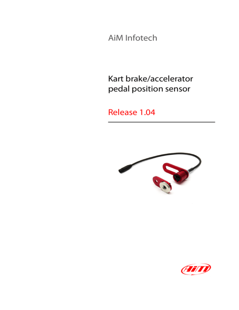
AiM Infotech Kart brake/accelerator pedal position sensor Release 1.04 This datasheet shows where and how to install the kart brake/accelerator pedal position sensor. 1 Introduction AiM devices can measure the distance between two points using a kart brake/accelerator pedal position sensor. It gives an extremely precise indication of the pedal position, measures its travel and shows all values in percentage in a 0 e 100%. range 2 Kits and spare parts The cable of kart brake/accelerator pedal position sensor ends with a 4 pins plastic Binder connector. It can be connected to both MyChron Expansion and eBox Extreme, which have metal connectors. This is why you need to purchase it with the correct extension cable. Available kits are: kit for connection with MyChron Expansion: part number X05SNAFME0. It includes: • 1 sensor (1) • 1 – 150 cm extension cable (2) • 1 bracket kit (3) including 1 magnetic bracket 1 “L” bracket, 2 washers, 1 M6x16 Allen screw, 1 nut kit for connection with eBox Extreme: part number X05SNAFEE0. It includes: • 1 sensor (1) • 1 – 100 cm extension cable (2) • 1 bracket kit (3) including 1 magnetic bracket, 1 “L” bracket, 2 washers, 1 M6x16 Allen screw, 1 nut 1 All kit components can be bought also as spare parts. Their part numbers are: • Bracket kit: DNKTKSSAF00 including: o 1 magnetic bracket o 1 “L” bracket o 2 wshers o 1 M6x16 Allen screw o 1 nut • • 150 cm extension cable for per MyChron Expansion: V02PCB15BTXG 100 cm extension cable for eBox Extreme: V02552960 2.1 Installation notes The sensor has to be installed on the pedal as shown in the images below. Please install the sensor so that the distance between magnet and sensor stays in a 5 – 40 mm range. 2 3 Dimensions and pinout The drawing below shows the sensors dimensions in millimeters [inches]. The sensor is sold with a 25 cm cable ending with a 4 pins Binder 719 male connector. The image here below shows its pinout from solder termination view. Binder connector pin Function 1 Analog signal 0-5 V 2 GND 3 Not connected 4 V reference (4.5V) 3


