ProDisc-L Surgical Technique
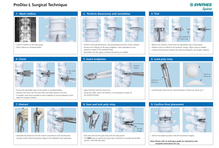
1. Mark midline
2. Perform discectomy and remobilize
3. Trial
screwdriver to
adjust stop
– Confirm midline via AP fluoroscopy.
– Mark midline on vertebral bodies.
– Perform thorough discectomy: free posterolateral corners of disc material.
– Preserve the integrity of the bony endplates: insert spreader(s) to the
posterior margin of the vertebral body.
– Remobilize the disc space; continue discectomy as needed.
4. Chisel
5. Insert endplates
– Before trial insertion, ensure that the adjustable stop is fully seated.
– Advance trial on midline to the posterior margin. Adjust stop as needed.
– Choose trial that best matches the anatomy (footprint, disc height, lordosis).
6. Load poly inlay
Posterior
margin
Two chisel
cuts
Dome up–
Dome up
Dome up–
Dome up
– Ensure the adjustable stop is fully seated on vertebral bodies.
– Advance the chisel over the trial shaft until fully seated on the trial.
– If needed, chisel twice (parallel to each endplate) to ensure adequate chisel
depth for implant insertion.
7. Distract
– Align the keels with the chisel cuts.
– Using the mallet, insert the ProDisc-L to the posterior margin of
the vertebral bodies.
– Load the poly inlay into the inserter grooves (“Dome-up, dome-up”).
8. Seat and lock poly inlay
9. Confirm final placement
No step
no gap
– Assemble the distractor into the inserter and advance with thumbscrew.
– Visually confirm that the posterior edge of the endplates have separated.
– Fully seat and lock the poly inlay with the inlay pusher.
– The ONLY way to confirm the poly inlay is locked is to visually and tactilely
confirm “NO STEP, NO GAP”.
– Verify final implant position with AP and lateral imaging.
Note: Please refer to technique guide for indications and
complete instructions for use.
ProDisc-L Surgical Technique
1. Mark midline
2. Perform discectomy and remobilize
– Confirm midline via AP fluoroscopy.
– Mark midline on vertebral bodies.
3. Trial
4. Chisel
5. Insert endplates
– Before trial insertion, ensure that the adjustable stop is fully seated.
– Advance trial on midline to the posterior margin. Adjust stop as needed.
– Choose trial that best matches the anatomy (footprint, disc height, lordosis).
6. Load poly inlay
Two chisel
cuts
Posterior margin
– Ensure the adjustable stop is fully seated on vertebral bodies.
– Advance the chisel over the trial shaft until fully seated on the trial.
– If needed, chisel twice (parallel to each endplate) to ensure adequate chisel
depth for implant insertion.
7. Distract
Dome up–
Dome up
– Align the keels with the chisel cuts.
– Using the mallet, insert the ProDisc-L to the posterior margin of
the vertebral bodies.
– Load the poly inlay into the inserter grooves (“Dome-up, dome-up”).
8. Seat and lock poly inlay
ProDisc and Synthes are trademarks of Synthes, Inc. or its affiliates.
Dome up–
Dome up
© 2009 Synthes, Inc. or its affiliates. All rights reserved.
– Perform thorough discectomy: free posterolateral corners of disc material.
– Preserve the integrity of the bony endplates: insert spreader(s) to the
posterior margin of the vertebral body.
– Remobilize the disc space; continue discectomy as needed.
9. Confirm final placement
Separated
endplates
No step
no gap
– Fully seat and lock the poly inlay with the inlay pusher.
– The ONLY way to confirm the poly inlay is locked is to visually and tactilely
confirm “NO STEP, NO GAP”.
– Verify final implant position with AP and lateral imaging.
Note: Please refer to technique guide for indications and
complete instructions for use.
Printed in U.S.A. 2/10 J9264-B
– Assemble the distractor into the inserter and advance with thumbscrew.
– Visually confirm that the posterior edge of the endplates have separated.


