Servo Motor LP, HC-RP, HC-UP Series> General
advertisement

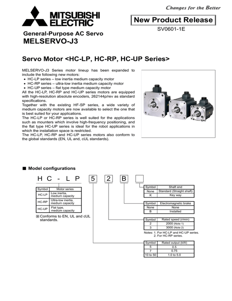
New Product Release SV0601-1E General-Purpose AC Servo MELSERVO-J3 Servo Motor <HC-LP, HC-RP, HC-UP Series> MELSERVO-J3 Series motor lineup has been expanded to include the following new motors: • HC-LP series – low inertia medium capacity motor • HC-RP series – ultra-low inertia medium capacity motor • HC-UP series – flat type medium capacity motor All the HC-LP, HC-RP and HC-UP series motors are equipped with high-resolution absolute encoders, 262144p/rev as standard specifications. Together with the existing HF-SP series, a wide variety of medium capacity motors are now available to select the one that is best suited for your applications. The HC-LP or HC-RP series is well suited for the applications such as mounters which involve high-frequency positioning, and the flat type HC-UP series is ideal for the robot applications in which the installation space is restricted. The HC-LP, HC-RP and HC-UP series motors also conform to the global standards (EN, UL and, cUL standards). Model configurations H C - L P Symbol HC-RP Motor series Low inertia, medium capacity Ultra-low inertia, medium capacity HC-UP Flat type, medium capacity HC-LP Conforms to EN, UL and cUL standards. 5 2 B Symbol Shaft end None Standard (Straight shaft) Key way K Symbol None B Electromagnetic brake None Installed Symbol 2 3 Rated speed (r/min) 2000 (Note 1) 3000 (Note 2) Notes: 1. For HC-LP and HC-UP series. 2. For HC-RP series. Symbol 5 7 10 to 50 Rated output (kW) 0.5 0.75 1.0 to 5.0 HC-LP series servo motor specifications Servo motor model (Note 7) Servo amplifier model (Note 6) Power facility capacity (Note 1) Rated output Continuous running duty Rated torque Maximum torque Rated speed Maximum speed Permissible instantaneous speed Power rate at continuous rated torque Rated current Maximum current Regenerative braking frequency (Note 2) HC-LP52(B) HC-LP102(B) HC-LP152(B) HC-LP202(B) HC-LP302(B) MR-J3-60A/B MR-J3-100A/B MR-J3-200A/B MR-J3-350A/B MR-J3-500A/B 1.0 0.5 2.39 (338) 7.16 (1010) 1.7 1.0 4.78 (677) 14.4 (2040) 2.5 1.5 7.16 (1010) 21.6 (3060) 2000 3000 3450 3.5 2.0 9.55 (1350) 28.5 (4040) 4.8 3.0 14.3 (2020) 42.9 (6070) (kW/s) 18.4 49.3 79.8 41.5 56.8 (A) (A) 3.2 9.6 5.9 18 9.9 30 14 42 23 69 (times/min) 115 160 425 120 70 3.10 (16.9) 4.62 (25.3) 6.42 (35.1) 22.0 (120) 36.0 (197) 5.20 (28.4) 6.72 (36.7) 8.52 (46.6) 32.0 (175) 46.0 (252) (kVA) (kW) (N•m [oz•in]) (N•m [oz•in]) (r/min) (r/min) (r/min) Moment of inertia Standard J (×10-4kg•m2) With electromagnetic brake [J (oz•in2)] Recommended load/motor inertia moment ratio Speed/position detector Attachments Insulation class Structure Environment Ambient temperature Ambient humidity Atmosphere Elevation / Vibration (Note 5) Mass (kg [lb]) Standard With electromagnetic brake 10 times the servo motor's inertia moment maximum (Note 3) 18-bit encoder (Resolution per encoder/servo motor rotation: 262144p/rev) Oil seal Class F Totally enclosed non ventilated (protection level: IP65) (Note 4) 0 to 40°C (32 to 104°F) (non freezing), storage: -15 to 70°C (5 to 158°F) (non freezing) 80%RH maximum (non condensing), storage: 90%RH maximum (non condensing) Indoors (no direct sunlight); no corrosive gas, inflammable gas, oil mist or dust 1000m or less above sea level/ 1000m or less above sea level/ X: 9.8m/s2 Y: 24.5m/s2 X: 19.6m/s2 Y: 49m/s2 6.5 (15) 8.0 (18) 10 (22) 21 (47) 28 (62) 9.0 (20) 11 (25) 13 (29) 27 (60) 34 (75) Notes: 1. The power facility capacity varies depending on the power supply's impedance. 2. The regenerative braking frequency shows the permissible frequency for decelerating the motor without a load and the optional regeneration unit from the rated speed to a stop. 3. Contact Mitsubishi if the load/motor of inertia moment ratio exceeds the value in the table. 4. The shaft-through portion is excluded. 5. The vibration direction is shown in the right-side diagram. The numeric value indicates the maximum value of the component (commonly the bracket in the opposite direction of the motor shaft). Fretting of the bearing occurs easily when X the motor stops, so maintain vibration to approximately one-half of the allowable value. 6. The amplifier software version compatible with the HC-LP series is as follows: A type: Version B0 or above B type: Version A0 or above 7. MRZJW3-SETUP221E software version B1 or above is planned to be compatible with the HC-LP series. HC-LP series servo motor torque characteristics Y (Note 1) HC-LP52(B) (Note 2, 3) Notes: 1. 2. 3. 2 : For 3-phase 200VAC. : For 1-phase 230VAC. : For 1-phase 200VAC. This line is drawn only where differs from the other two lines. HC-LP series servo motor dimensions HC-LP52(B), HC-LP102(B), HC-LP152(B) (Unit: mm) L 130 55 12 50 38 (Note 3) 4- 9 mounting hole Use hexagonal cap head bolts. 3 45° (Note 3) (Note 3) 50.9 5 14 16 5 Oil seal S30457B 111 (Note 3) 110h7 24h6 (Note 3) 13 Encoder connector CM10-R10P KL Brake (Note 3) Power supply connector CE05-2A22-23P Earth 44 U EF D G CH A B W V Power supply connector pin assignment Motor flange direction Variable dimensions L KL 144 HC-LP52(B) 77 (177) 164 HC-LP102(B) 97 (197) 191.5 HC-LP152(B) 124.5 (224.5) Model Brake static friction torque (N·m [oz·in]) Model HC-LP52B 8.5 (1200) HC-LP102B HC-LP152B HC-LP202(B), HC-LP302(B) 79 L 18 75 2 (Note 3) (Note 3) Oil seal S40608B 1 20 2 13 67.5 Encoder connector CM10-R10P (Note 3) KL 46 A B Power supply connector CE05-2A24-10P W 1 and 2 are screw holes for hanging bolt (M8). The screw holes are only for HC-LP302(B). Variable dimensions L KL 198.5 HC-LP202(B) 123.5 (246.5) 248.5 HC-LP302(B) 173.5 (296.5) Model U Earth Brake Brake connector MS3102A10SL-4P (Note 3) Model HC-LP202B HC-LP302B Brake connector pin assignment Motor flange direction (Note 3) E F DG C A B V Power supply connector pin assignment Motor flange direction Brake static friction torque (N·m [oz·in]) 44 (6230) Notes: 1. Use a friction coupling to fasten a load. 2. Dimensions inside ( ) are for the models with an electromagnetic brake. 3. Only for the models with an electromagnetic brake. The electromagnetic brake terminals do not have the polarity. 4. For dimensions where there is no tolerance listed, use general tolerance. 3 0 0 114.3-0.025 50.9 (Note 3) 23 0 142 1 (Note 3) 117 (Note 3) (Note 3) 4- 13.5 mounting hole Use hexagonal cap head bolts. 45° 35 +0.010 0 38 (Note 3) 176 3 HC-RP series servo motor specifications Servo motor model (Note 7) Servo amplifier model (Note 6) HC-RP103(B) HC-RP153(B) HC-RP203(B) MR-J3-200A/B HC-RP353(B) MR-J3-350A/B HC-RP503(B) MR-J3-500A/B Power facility capacity (Note 1) (kVA) Rated output (kW) Continuous running duty Rated torque (N•m [oz•in]) Maximum torque (N•m [oz•in]) Rated speed (r/min) Maximum speed (r/min) Permissible instantaneous speed (r/min) Power rate at continuous rated (kW/s) torque Rated current (A) Maximum current (A) Regenerative braking frequency (times/min) 1.7 1.0 3.18 (450) 7.95 (1130) 2.5 1.5 4.78 (677) 11.9 (1690) 3.5 2.0 6.37 (902) 15.9 (2250) 3000 4500 5175 5.5 3.5 11.1 (1570) 27.9 (3950) 7.5 5.0 15.9 (2250) 39.7 (5620) 67.4 120 176 150 211 6.1 18 8.8 23 14 37 23 58 28 70 1090 860 710 174 125 Moment of inertia Standard J (×10-4kg•m2) With electromagnetic brake [J (oz•in2)] Recommended load/motor inertia moment ratio 1.50 (8.20) 1.90 (10.4) 2.30 (12.6) 8.30 (45.4) 12.0 (65.6) 1.85 (10.1) 2.25 (12.3) 2.65 (14.5) 11.8 (64.5) 15.5 (84.7) (Note 2) Speed/position detector Attachments Insulation class Structure Ambient temperature Ambient humidity Atmosphere Environment Elevation / Vibration (Note 5) Standard With electromagnetic brake Mass (kg [lb]) 5 times the servo motor's inertia moment maximum (Note 3) 18-bit encoder (Resolution per encoder/servo motor rotation: 262144p/rev) Oil seal Class F Totally enclosed non ventilated (protection level: IP65) (Note 4) 0 to 40°C (32 to 104°F) (non freezing), storage: -15 to 70°C (5 to 158°F) (non freezing) 80%RH maximum (non condensing), storage: 90%RH maximum (non condensing) Indoors (no direct sunlight); no corrosive gas, inflammable gas, oil mist or dust 1000m or less above sea level/ X, Y: 24.5m/s2 3.9 (8.6) 5.0 (11) 6.2 (14) 12 (27) 17 (38) 6.0 (14) 7.0 (16) 8.3 (19) 15 (33) 21 (47) Notes: 1. The power facility capacity varies depending on the power supply's impedance. 2. The regenerative braking frequency shows the permissible frequency for decelerating the motor without a load and the optional regeneration unit from the rated speed to a stop. 3. Contact Mitsubishi if the load/motor of inertia moment ratio exceeds the value in the table. 4. The shaft-through portion is excluded. 5. The vibration direction is shown in the right-side diagram. The numeric value indicates the maximum value of the component (commonly the bracket in the opposite direction of the motor shaft). Fretting of the bearing occurs easily when X the motor stops, so maintain vibration to approximately one-half of the allowable value. 6. The amplifier software version compatible with the HC-RP series is as follows: A type: Version B0 or above B type: Version A0 or above 7. MRZJW3-SETUP221E software version B1 or above is planned to be compatible with the HC-RP series. HC-RP series servo motor torque characteristics HC-RP103(B) 1260 9 840 6 420 3 0 Peak running range Continuous running range 0 1000 2000 3000 4000 4500 15 1400 10 700 5 Peak running range 0 0 1000 2000 3000 4000 4500 Speed (r/min) HC-RP353(B) 30 20 1400 10 0 Continuous running range 0 1000 2000 3000 4000 4500 18 1680 12 840 6 Peak running range Continuous running range 0 0 1000 2000 3000 4000 4500 Speed (r/min) HC-RP503(B) 6300 45 4200 30 2100 15 Peak running range 2800 HC-RP203(B) 2520 Continuous running range Speed (r/min) 4200 (Note) HC-RP153(B) 2100 Peak running range Continuous running range 0 0 1000 2000 3000 4000 4500 Speed (r/min) Speed (r/min) 4 Y Note: : For 3-phase 200VAC. HC-RP series servo motor dimensions HC-RP103(B), HC-RP153(B), HC-RP203(B) (Unit: mm) 45 L 10 40 (Note 3) (Note 3) (Note 3) 50.9 95h7 (Note 3) 45° 4- 9 mounting hole Use hexagonal cap head bolts. 24h6 38 (Note 3) 100 3 13 5 5 11 Oil seal S30457B 96 (Note 3) 13 44 KL Encoder connector CM10-R10P Brake (Note 3) Earth Power supply connector CE05-2A22-23P EF D C HA G B W U V Power supply connector pin assignment Motor flange direction Variable dimensions L KL 145.5 HC-RP103(B) 69.5 (183.5) 170.5 HC-RP153(B) 94.5 (208.5) 195.5 HC-RP203(B) 119.5 (233.5) Model Model Brake static friction torque (N·m [oz·in]) HC-RP103B 7 (991) HC-RP153B HC-RP203B HC-RP353(B), HC-RP503(B) L 130 63 12 3 38 58 45° 110h7 (Note 3) 16 5 5 14 Oil seal S30457B 120 (Note 3) 50.9 (Note 3) 28h6 (Note 3) 13 Encoder connector CM10-R10P KL 46 Brake (Note 3) Earth Power supply connector CE05-2A24-10P DE F G C W B A U V Power supply connector pin assignment Motor flange direction Variable dimensions L KL 215.5 HC-RP353(B) 148 (252.5) 272.5 HC-RP503(B) 205 (309.5) Model 4- 9 mounting hole Use hexagonal cap head bolts. Model HC-RP353B HC-RP503B Brake static friction torque (N·m [oz·in]) 17 (2410) Notes: 1. Use a friction coupling to fasten a load. 2. Dimensions inside ( ) are for the models with an electromagnetic brake. 3. Only for the models with an electromagnetic brake. The electromagnetic brake terminals do not have the polarity. 4. For dimensions where there is no tolerance listed, use general tolerance. 5 HC-UP series servo motor specifications Servo motor model (Note 7) Servo amplifier model (Note 6) HC-UP72(B) HC-UP152(B) HC-UP202(B) MR-J3-70A/B MR-J3-200A/B MR-J3-350A/B Power facility capacity (Note 1) (kVA) Rated output (kW) Continuous running duty Rated torque (N•m [oz•in]) Maximum torque (N•m [oz•in]) Rated speed (r/min) Maximum speed (r/min) Permissible instantaneous speed (r/min) Power rate at continuous rated (kW/s) torque Rated current (A) Maximum current (A) Regenerative braking frequency (times/min) 1.3 0.75 3.58 (507) 10.7 (1520) 2.5 1.5 7.16 (1010) 21.6 (3060) 3.5 2.0 9.55 (1350) 28.5 (4040) 2000 Moment of inertia Standard J (×10-4kg•m2) With electromagnetic brake [J (oz•in2)] Recommended load/motor inertia moment ratio (Note 2) Speed/position detector Attachments Insulation class Structure Ambient temperature Ambient humidity Atmosphere Environment Elevation / Vibration (Note 5) Standard With electromagnetic brake Mass (kg [lb]) HC-UP352(B) HC-UP502(B) MR-J3-500A/B 5.5 3.5 16.7 (2360) 50.1 (7090) 3000 3450 7.5 5.0 23.9 (3380) 71.6 (10100) 2500 2875 12.3 23.2 23.9 36.5 49.6 5.4 16 9.7 29 14 42 23 69 28 84 53 124 68 44 31 10.4 (56.9) 22.1 (121) 38.2 (209) 76.5 (418) 115 (629) 12.5 (68.3) 24.2 (132) 46.8 (256) 85.1 (465) 124 (678) 15 times the servo motor's inertia moment maximum (Note 3) 18-bit encoder (Resolution per encoder/servo motor rotation: 262144p/rev) Oil seal Class F Totally enclosed non ventilated (protection level: IP65) (Note 4) 0 to 40°C (32 to 104°F) (non freezing), storage: -15 to 70°C (5 to 158°F) (non freezing) 80%RH maximum (non condensing), storage: 90%RH maximum (non condensing) Indoors (no direct sunlight); no corrosive gas, inflammable gas, oil mist or dust 1000m or less above sea level/ 1000m or less above sea level/ X, Y: 24.5m/s2 X: 24.5m/s2 Y: 49m/s2 8.0 (18) 11 (25) 16 (36) 20 (44) 24 (53) 10 (22) 13 (29) 22 (49) 26 (58) 30 (67) Notes: 1. The power facility capacity varies depending on the power supply's impedance. 2. The regenerative braking frequency shows the permissible frequency for decelerating the motor without a load and the optional regeneration unit from the rated speed to a stop. 3. Contact Mitsubishi if the load/motor of inertia moment ratio exceeds the value in the table. 4. The shaft-through portion is excluded. 5. The vibration direction is shown in the right-side diagram. The numeric value indicates the maximum value of the component (commonly the bracket in the opposite direction of the motor shaft). Fretting of the bearing occurs easily when X the motor stops, so maintain vibration to approximately one-half of the allowable value. 6. The amplifier software version compatible with the HC-UP series is as follows: A type: Version B0 or above B type: Version A0 or above 7. MRZJW3-SETUP221E software version B1 or above is planned to be compatible with the HC-UP series. HC-UP series servo motor torque characteristics HC-UP72(B) (Note 2, 3) 1680 12 8 560 4 2240 16 1120 8 0 1000 2000 3000 0 0 5600 40 2800 0 Peak running range 10 1000 2000 Continuous running range 3000 0 0 1000 2000 Speed (r/min) 80 8400 60 Peak running 5600 40 2800 20 range Continuous running range 1000 1400 HC-UP502(B) 11200 20 0 20 Speed (r/min) HC-UP352(B) 60 2800 Continuous running range Speed (r/min) 8400 30 Peak running range Peak running range Continuous running range 0 HC-UP202(B) 4200 24 Peak running range 1120 (Note 1) HC-UP152(B) 3360 2000 2500 Speed (r/min) 0 Continuous running range 0 1000 2000 2500 Speed (r/min) 6 Y Notes: 1. 2. 3. : For 3-phase 200VAC. : For 1-phase 230VAC. : For 1-phase 200VAC. This line is drawn only where differs from the other two lines. 3000 HC-UP series servo motor dimensions HC-UP72(B), HC-UP152(B) (Unit: mm) L 176 55 13 3 38 50 40° 45° 4- 13.5 mounting hole Use hexagonal cap head bolts. 2-M6 screw Sh6 (Note 3) 20 0 0 114.3 -0.025 (Note 3) 50.9 (Note 3) 23 0 (Note 3) 5 21 (Note 3) Oil seal S30457B 144 13 Encoder connector CM10-R10P Brake (Note 3) Earth Power supply connector CE05-2A22-23P EF KL W D CHA B G U 44 V Power supply connector pin assignment Motor flange direction Variable dimensions L KL S 109 HC-UP72(B) 38 22 (142.5) 118.5 HC-UP152(B) 47.5 28 (152) Model Brake static friction torque (N·m [oz·in]) Model HC-UP72B 8.5 (1200) HC-UP152B HC-UP202(B), HC-UP352(B), HC-UP502(B) L 4 38 35 +0.010 0 (Note 3) 42 (Note 3) KL 47 Model U Earth Brake E F D G A B C W Brake connector pin assignment Motor flange direction (Note 3) Variable dimensions L KL 116.5 HC-UP202(B) 42.5 (159.5) 140.5 66.5 HC-UP352(B) (183.5) 164.5 HC-UP502(B) 90.5 (207.5) 5 23 270 165 Encoder connector 53.5 (Note 3) CM10-R10P Brake connector MS3102A10SL-4P (Note 3) Power supply connector CE05-2A24-10P Model 4- 13.5 mounting hole Use hexagonal cap head bolts. Oil seal S40608B 13 (Note 3) 45° 200h7 50.9 139 (Note 3) (Note 3) 2-M8 screw ° 37.5 0 25 (Note 3) 60 (Note 3) (Note 3) 220 65 16 B A V Power supply connector pin assignment Motor flange direction Brake static friction torque (N·m [oz·in]) HC-UP202B HC-UP352B 44 (6230) HC-UP502B Notes: 1. Use a friction coupling to fasten a load. 2. Dimensions inside ( ) are for the models with an electromagnetic brake. 3. Only for the models with an electromagnetic brake. The electromagnetic brake terminals do not have the polarity. 4. For dimensions where there is no tolerance listed, use general tolerance. 7 MEMO SV0601-1E <MEE>


