Digital and Pulse-Train Conditioning
advertisement

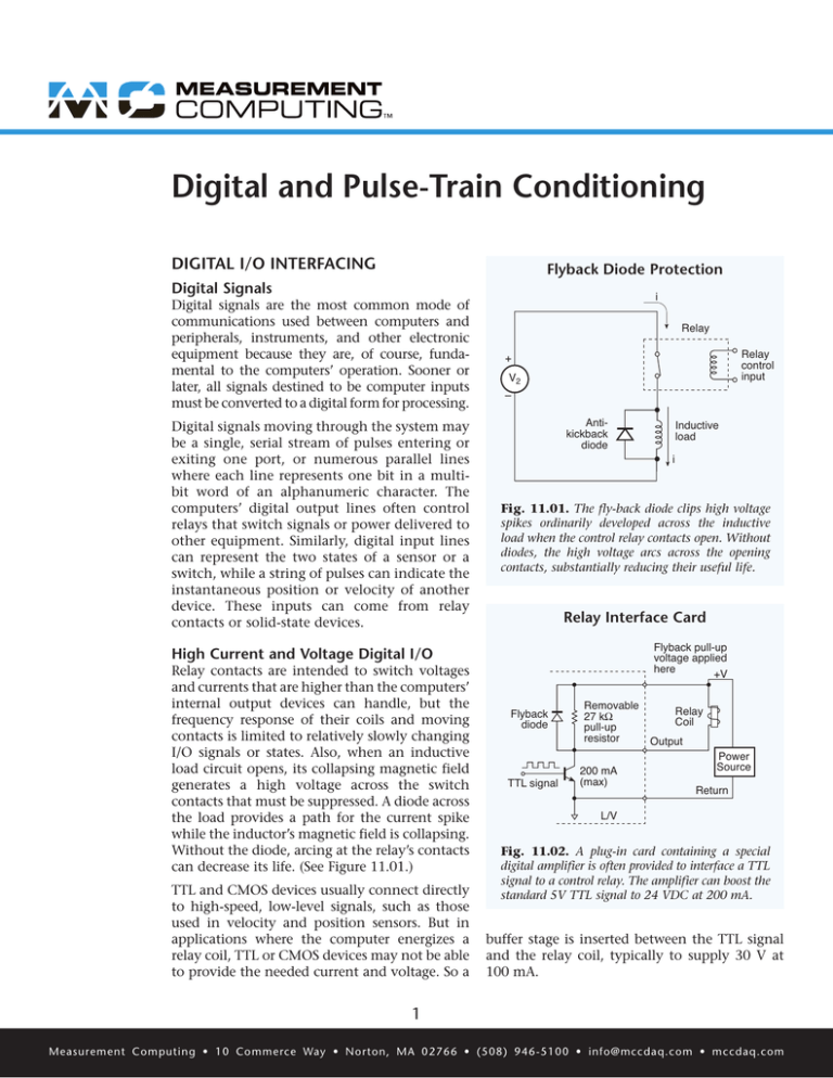
Digital and Pulse-Train Conditioning DIGITAL I/O INTERFACING Flyback Diode Protection Digital Signals Digital signals are the most common mode of communications used between computers and peripherals, instruments, and other electronic equipment because they are, of course, fundamental to the computers’ operation. Sooner or later, all signals destined to be computer inputs must be converted to a digital form for processing. Digital signals moving through the system may be a single, serial stream of pulses entering or exiting one port, or numerous parallel lines where each line represents one bit in a multibit word of an alphanumeric character. The computers’ digital output lines often control relays that switch signals or power delivered to other equipment. Similarly, digital input lines can represent the two states of a sensor or a (8.01) the switch, while a string ofFigure pulses11.01 can indicate instantaneous position or velocity of another device. These inputs can come from relay contacts or solid-state devices. i Relay Relay control input + V2 – Antikickback diode TTL and CMOS devices usually connect directly to high-speed, low-level signals, such as those used in velocity and position sensors. But in Figure 11.03 (8.03) applications where the computer energizes a relay coil, TTL or CMOS devices may not be able to provide the needed current and voltage. So a i Fig. 11.01. The fly-back diode clips high voltage spikes ordinarily developed across the inductive load when the control relay contacts open. Without diodes, the high voltage arcs across the opening contacts, substantially reducing their useful life. Relay Interface Card Flyback pull-up voltage applied here +V High Current and Voltage Digital I/O Relay contacts are intended to switch voltages and currents that are higher than the computers’ internal output devices can handle, but the frequency response of their coils and moving contacts is limited to relatively slowly changing I/O signals or states. Also, when an inductive load circuit opens, its collapsing magnetic field generates a high voltage across the switch contacts that must be suppressed. A diode across the load provides a path for the current spike while the inductor’s magnetic field is collapsing. Without the diode, arcing at the relay’s contacts can decrease its life. (See Figure 11.01.) Inductive load Flyback diode TTL signal Removable 27 kΩ pull-up resistor 200 mA (max) Relay Coil Output Power Source Return L/V Fig. 11.02. A plug-in card containing a special digital amplifier is often provided to interface a TTL signal to a control relay. The amplifier can boost the standard 5V TTL signal to 24 VDC at 200 mA. buffer stage is inserted between the TTL signal and the relay coil, typically to supply 30 V at 100 mA. 1 Measurement Computing • 10 Commerce Way • Norton, MA 02766 • (508) 946-5100 • info@mccdaq.com • mccdaq.com Asynchronous Digital-Input Readings Relay Interface Card A software-triggered, asynchronous reading is required when the computer periodically samples a digital byte or a group of bits. And sometimes the speed and timing of the digital-input readings are particularly critical. But the time between readings is likely to vary when using the softwaretriggered, single-byte method, particularly in applications running under a multitasking operating system such as in a PC. The reason is that the time between readings depends on the speed of the computer and other tasks that must be performed concurrently. Variations in time between readings can be partially compensated with software timers, but a timing resolution of less than 10 ms is not guaranteed on a PC. TTL input User input Resistor in DIP package R 15 kΩ Fig. 11.03. One optional interface card comes with an adjustable attenuator to handle an input range from 5 to 48V in four steps. The table specifies the voltage levels that can be selected with four different resistors. Synchronous Digital-Input Readings Some systems offer hardware-paced digital input readings. In such systems, the user sets the frequency that the digital input port can read. For example, one system can read its 16-bit port at 100 kHz, while another operates to 1 MHz. The greatest advantage of hardware-based digital input readings is that they can be implemented far more quickly than can software-triggered readings. Finally, devices such as these can locate the digital-input port readings among the analog readings, providing a close correlation between analog and digital input data. Typical Voltage Levels & Associated Resistor Values 11.04A (8.04) Inputs Resistor Value, R 0 to 5 V 10 Ω 0 to 12 V 20 kΩ 0 to 24 V 56 kΩ 0 to 48 V 120 kΩ Fig. 11.04. Typical voltage levels and resistor values. Externally Triggered Digital-Input Readings Some external devices provide a digital bit, byte, or word at a rate independent of the data acquisition system. They take readings only when new data are available rather than at a predetermined interval. Because of this, such external devices typically transfer data through a handshaking technique. As new digital information becomes available, the external device issues a digital transition on a separate line, such as an External Data Ready or Strobe input. To interface with a device like this, the data acquisition system must provide an input latch, which the external signal controls. Furthermore, a logic signal supplied to the controlling computer alerts it to the fact that new data are ready to be received from the latch. An example of this type of system is an optional card for a digital I/O instrument. It contains an amplifier/attenuator stage, consisting of a PNP transistor, a fly-back diode, and a resistor. (See Figure 11.02.) To energize a standard 24 V relay, an external 24 V supply is connected to the circuit. As the internal TTL output goes high, the transistor is biased and the output goes low, (about 0.7 V). When the TTL output is low, the transistor stops conducting and the output goes to 24 V. Since the relay coil is an inductive load, the fly-back diode should be attached to prevent damage during switching. Figure 11.03 shows a high-voltage digital input with an attenuator circuit. This allows the TTL circuitry to read voltages up to 48 V. The high-voltage signal connects to a resistive voltage divider, which is a signal attenuator. Selecting an appropriate resistance value R provides a means for selecting the high-voltage level. The table in Figure 11.04 shows the resistor values for frequently used levels. One example of a device that operates in this fashion has an inhibit line among its six handshake/control lines for notifying external devices that the input latch is being read. This procedure lets the external device hold new digital information until the current read event is performed successfully. DIGITAL ISOLATION DIGITAL INPUTS Digital signals often are isolated for several reasons: To protect each side of the system from an inadvertent overvoltage condition on the opposite side, to facilitate communication between devices with different grounds, and to prevent injury when circuits are attached to people in medical applications. One common approach The methods used for interfacing digital inputs to a computer range from simple to complex. This section briefly discusses software-triggered, single-byte readings; hardware-paced, digital input readings; and externally triggered, digital-input readings. 2 Measurement Computing • 10 Commerce Way • Norton, MA 02766 • (508) 946-5100 • info@mccdaq.com • mccdaq.com 6 Optical Coupler Isolation High Vcc 1.8k 47k Digital interface 4N28 Control 2 Address 6 Data 8 To data acquisition system Digital inputs Low One opto-isolator Fig. 11.05. An optical isolator decouples the digital signal source ground from the data acquisition system ground, and protects the acquisition system inputs from unintentional high voltages. levels, and the analog input circuit converts a timevarying signal into a clean digital pulse train. Analog to Pulse Converter Figure 11.05 BNC 0.33 µF 20 kΩ Attenuate 1:1 or 1:50 Figure 11.06 shows the schematic of the analog input, signal-conditioning path. The front-end RC network provides AC coupling allowing all signals above about 25 Hz to pass. The selectable attenuator reduces the overall magnitude of the waveform to desensitize the circuit from unwanted low-level noise. When using a pulse train from a relay closure, the unit provides programmable settings that let the user select the amount of debounce time required. The digital circuitry monitors the conditioned pulse-train for a sustained high or low level. Without debouncing, the extra edges in the signal produce an excessively high and erratic frequency reading. (See Figure 11.07.) Filter 100 kHz 300 kHz or 30 Hz Fig. 11.06. An interface circuit contains an RC network that significantly attenuates AC signals below 25 Hz before converting the higher frequencies to a digital pulse stream. Many transducers generate frequency-modulated output signals rather than amplitude-modulated. For instance, sensors that measure rotational motion and fluid flow typically fall into this class. Photomultiplier tubes and charged-particle detectors also are often used for measurements that require pulse counting. In principle, such signals could be sampled with an ADC, but this approach generates much more data than necessary and makes the analysis cumbersome. Direct frequency measurements are far more efficient. for isolation is through an optical coupler. Optical coupling consists of an LED or diode laser to transmit the digital signal and a photodiode or phototransistor to receive it. (See Figure 11.05.) Small optical couplers isolate voltages up to 500 V. For example, this technique effectively controls and monitors digital devices connected between dissimilar grounds. PULSE TRAIN SIGNAL CONDITIONING In many frequency-measurement applications, pulses are counted and compared against a fixed time base. A pulse can be considered a digital signal because only the number of rising or falling edges is measured. In many instances, however, the pulse-train signal comes from an analog source, such as a magnetic pickup. FREQUENCY-TO-VOLTAGE CONVERSION Data acquisition systems measure frequency in several ways; they integrate a continuous wave AC signal or pulse trains to produce a DC voltage with a magnitude proportional to the frequency, convert the AC voltage to a binary digital signal with an ADC, or count digital pulses. For example, one widely used input frequency card in a data acquisition system provides four channels of frequency input through two separate front-end circuits, one for true digital input circuits and one for analog inputs. The card conditions digital inputs of different Pulse-Train Integration One conversion technique commonly used in a singlechannel, modular signal conditioner integrates the input 3 Measurement Computing • 10 Commerce Way • Norton, MA 02766 • (508) 946-5100 • info@mccdaq.com • mccdaq.com Debounce Feature Sustained low "Bouncy" input Ignored edges a b c Sustained low d e Pulse-Train Integration Ignored edges Raw input After initial signal conditioning f Debounced output Time (ms) Conditioned signal has constant pulse width Integrated output voltage 0 10 20 30 40 50 60 Fig. 11.08. In one type of frequency-to-voltage converter, an integrator circuit converts a string of constant-width pulses of varying repetition rate into a smoothly changing analog voltage. The analog signal is proportional to the input frequency. Fig. 11.07. A relay contact debounce circuit filters extraneous signals that the measurement amplifier could mistake for rising and falling edges of a legitimate string of signal pulses. pulses and produces an output voltage proportional to Figurecouples 11.08 the AC the frequency. First, a series capacitor signal, which removes extremely low frequency AC and DC components. A comparator generates a constant pulse width each time the input signal passes through zero. The pulse then passes through an integrating circuit such as a low-pass filter and generates a slowly changing signal level at its output, proportional to the input frequency. (See Figure 11.08.) Output Ripple Low frequency pulses Integrated output The response time of the frequency-to-voltage converter is low – the inverse of the cutoff frequency of the low-pass filter. This cutoff frequency should be much lower than the input frequencies being measured, but high enough to provide the required response time. As the measured frequency approaches the cutoff frequency however, significant ripple in the output becomes a problem as shown in Figure 11.09. Fig. 11.09. The pulse-train integrator handles only frequencies above a certain cutoff, due to the integrator’s time constant. Frequencies below cutoff produce output ripple if allowed to pass. For example, the analog input channel of a typical frequency-input data acquisition card contains a lowpass filter with a selectable cutoff frequency of 100 kHz, 300 Hz, or 30 Hz. It measures frequencies from 1 Hz to 100 kHz for signals ranging from 50 mV to 80 Vp-p. The digital input circuit measures ±15 VDC signals from 0.001 Hz to 950 kHz, dc-coupled to a TTL Schmidt trigger circuit. The cards typically come with pull-up resistors for use with relays or switches. An external capacitor selects the time constant Figure 11.09for an IC dedicated to frequency to voltage conversion. The circuit can measure signals in vastly different fixed frequency ranges, but the capacitor must be changed to change a frequency range. Unfortunately, such frequency-to-voltage converters work relatively poorly for frequencies below 100 Hz because a low-pass filter with a cutoff frequency under 10 Hz requires an excessively large capacitor. A microcontroller accurately measures a total period consisting of several cycles extending over one userselectable minimal period, which determines the frequency resolution. The microcontroller computes the frequency from the measured period and converts it to a command for a DAC, which, in turn, provides the DC level to the data acquisition system. The DC output of the DAC drives the input of an ordinary DC signal conditioner, and the software converts the DC level to an equivalent frequency reading. This method allows extremely low frequencies to be measured over an exceptionally wide range, and the output update can be relatively fast. Moreover, the Digital-Pulse Counting Another type of conversion technique measures the frequency of a string of digital pulses or an ac-coupled analog signal voltage. It outputs a DC voltage level proportional to the input frequency, similar to the integrator described above. However, the DC level here comes from a DAC output. Front-end circuitry converts the incoming analog or digital signal into a clean pulse train, devoid of relay contact bounce, high-frequency noise, and other unwanted artifacts before it reaches the DAC. (See Figure 11.10.) 4 Measurement Computing • 10 Commerce Way • Norton, MA 02766 • (508) 946-5100 • info@mccdaq.com • mccdaq.com Digital Pulse Counting Jumpers shown configured for analog input mode Schmitt-trigger buffer Digital input mode BNC Frequency measurement Analog input mode Selectable attenuator a DAC To data acquisition system LPF f Microprocessor-based frequency measurement circuit Low pass filter Channel 0 Fig. 11.10. In the other type of frequency-to-voltage converter, the input card contains an input coupling capacitor to filter low frequencies, an attenuator, a low pass filter, and a microprocessor to calculate the frequency. The signal is then connected to a DAC before feeding into the data acquisition system. frequency range can be programmed, letting the expected frequencies use the entire ADC range. Frequency Measurement by Gated-Pulse Counting Gated-pulse counting can measure frequencies much more accurately than frequency-to-voltage conversion methods. Gated-pulse counting methods count the pulses that appear over a specified period of time. Dividing the number of pulses by the counting interval determines the frequency, and the error can be as low as the inverse of the counting interval. For example, if the counting interval is two seconds, the error can be as low as 0.5 Hz. Figure 11.10 range of the DAC is +5 to -5 V. The miniThe output mum frequency selected by the user becomes the -5 V output while the maximum frequency becomes +5 V. Virtually any frequency bandwidth may be selected such as 500 Hz Fmin to 10 kHz Fmax, or 59.5 Hz Fmin to 60.5 Hz Fmax. With an ADC of 12-bit resolution, the lower bandwidths will have higher resolution than higher bandwidths, simply because the range from -5 to +5 VDC is partitioned into 4096 parts regardless of bandwidth. The one-Hz bandwidth is divided into 4096 parts, which yields a resolution of 1/4096 Hz or about 0.00244 Hz. For the 100 kHz bandwidth, the resolution becomes 24.41 Hz. Many data acquisition systems include TTL-compatible counter/timer ICs that can perform gated-pulse, digitallevel input, however, they are unsuitable for unconditioned analog signals. Fortunately, many frequency-output devices feature a TTL output option. Some products use a counter/timer IC, which contains five counter/timers. Many counter/timer ICs generally use an oscillator built into the data acquisition system, or an external oscillator. Such ICs usually have several channels available to assist counting applications. Each channel contains an input, a gate, and an output. The simplest counting method only uses the input, and the PC is programmed to periodically read and reset the counter. The weakness in this approach is the uncertainty in the timing interval. Variations crop up in the execution speeds of the functions that begin and end counting. In addition, the function call that delays execution of the program for 50 ms runs under an inaccurate software timer. These two effects can render a short-counting interval, frequency measurement useless. However, the technique is usually sufficient for counting intervals greater than one second. The resolution is 12 bits over all ranges, but the update time depends on the range selected. From 1 Hz to the user-defined maximum upper range boundary, the voltage conversion update is 2 to 4 ms or the period of the input frequency, whichever is greater. For a range of 0 to 10 kHz, the update rate is 2 to 4 ms, and for a range of 0 to 60 Hz, the output updates every cycle or 16.6 ms. As the conversion range becomes narrower, from 49 to 51 Hz, for example, the time to resolve the 2-Hz differential to 12-bit resolution increases. In this case, the conversion time is approximately 59 ms. In addition to the low-pass filter, a predefined hysteresis level is built in to help prevent false counting caused by high-frequency noise. A debounce time can be programmed from 0.6 ms to 10 ms for handling electromechanical devices such as switch or relay contacts that bounce or chatter while switching. 5 Measurement Computing • 10 Commerce Way • Norton, MA 02766 • (508) 946-5100 • info@mccdaq.com • mccdaq.com Timing Applications Gating can attain greater accuracy because the gate controls the counting interval. Consequently, frequency measurements are independent of any software timing issues. The gate can be configured so that pulses are counted only when a high-level signal enters it. Similarly, the gate can start counting when it detects one pulse and stop counting when it detects another. A counter/timer also can be used in a data acquisition system for timing applications. A clock signal connected to the input of a channel and using the input signal as a gate works well. The method requires that the gate be configured for counting when the gate input is high. A similar technique can measure the length of time elapsed between two pulses by configuring the gate to begin counting at the first pulse and end counting at the second. A disadvantage of gated-pulse counting is that it requires an extra counter to provide the gate. However, in multiple channel applications, a single counter can provide the gate for many channels. For example, in a five-channel system, four channels count while one channel provides a gate. Because a 16-bit counter overflows at 65,535 counts, the maximum pulse width measurable with a 1 MHz clock is 65,535 ms; a longer pulse overflows the counter. However, a clock slower than 1 MHz can be used for longer pulses. Data Acquisition Solutions Digital I/O boards AND modules Electromechanical relay modules • 24 digital I/O lines • 8 or 24 relays • High current output available • Form C (SPDT) relays • 37-pin connector • 6 amps at 240 VAC/28 VDC • One 32-bit counter • Included software and drivers USB-DIO24 Series USB-ERB Series • Included software and drivers Counter/Timer boards and modules Digital Modules for solid state I/O • 5 or 10 channels • 8 or 24 input or output channels • Input frequencies up to 20 MS/s • Control and monitor up to 24 channels • Event counting, PWM, duty cycle generation, frequency measurement/division, and more • Uses standard OAC5/ODC5/IAC5/IDC5 modules (sold separately) • 16 digital I/O • Included software and drivers USB-4300 Series USB-SSR Series • Included software and drivers 6 Measurement Computing • 10 Commerce Way • Norton, MA 02766 • (508) 946-5100 • info@mccdaq.com • mccdaq.com


