VDE Information
advertisement
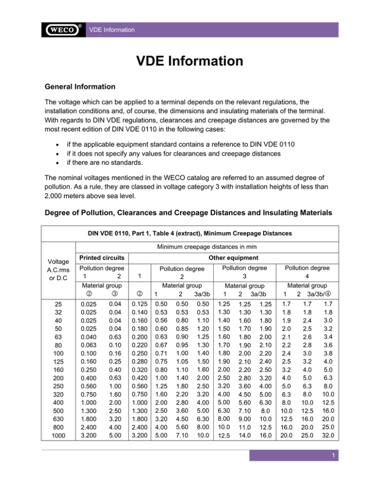
VDE Information VDE Information General Information The voltage which can be applied to a terminal depends on the relevant regulations, the installation conditions and, of course, the dimensions and insulating materials of the terminal. With regards to DIN VDE regulations, clearances and creepage distances are governed by the most recent edition of DIN VDE 0110 in the following cases: • • • if the applicable equipment standard contains a reference to DIN VDE 0110 if it does not specify any values for clearances and creepage distances if there are no standards. The nominal voltages mentioned in the WECO catalog are referred to an assumed degree of pollution. As a rule, they are classed in voltage category 3 with installation heights of less than 2,000 meters above sea level. Degree of Pollution, Clearances and Creepage Distances and Insulating Materials DIN VDE 0110, Part 1, Table 4 (extract), Minimum Creepage Distances Minimum creepage distances in mm Printed circuits Voltage A.C.rms or D.C Pollution degree 1 2 Material group 25 32 40 50 63 80 100 125 160 200 250 320 400 500 630 800 1000 Other equipment 1 2 3 2 0.025 0.025 0.025 0.025 0.040 0.063 0.100 0.160 0.250 0.400 0.560 0.750 1.000 1.300 1.800 2.400 3.200 0.04 0.04 0.04 0.04 0.63 0.10 0.16 0.25 0.40 0.63 1.00 1.60 2.00 2.50 3.20 4.00 5.00 0.125 0.140 0.160 0.180 0.200 0.220 0.250 0.280 0.320 0.420 0.560 0.750 1.000 1.300 1.800 2.400 3.200 Pollution degree 2 Material group 1 2 3a/3b 0.50 0.53 0.56 0.60 0.63 0.67 0.71 0.75 0.80 1.00 1.25 1.60 2.00 2.50 3.20 4.00 5.00 0.50 0.53 0.80 0.85 0.90 0.95 1.00 1.05 1.10 1.40 1.80 2.20 2.80 3.60 4.50 5.60 7.10 0.50 0.53 1.10 1.20 1.25 1.30 1.40 1.50 1.60 2.00 2.50 3.20 4.00 5.00 6.30 8.00 10.0 Pollution degree 3 Material group 1 2 3a/3b 1.25 1.30 1.40 1.50 1.60 1.70 1.80 1.90 2.00 2.50 3.20 4.00 5.00 6.30 8.00 10.0 12.5 1.25 1.30 1.60 1.70 1.80 1.90 2.00 2.10 2.20 2.80 3.60 4.50 5.60 7.10 9.00 11.0 14.0 1.25 1.30 1.80 1.90 2.00 2.10 2.20 2.40 2.50 3.20 4.00 5.00 6.30 8.0 10.0 12.5 16.0 Pollution degree 4 Material group 1 2 3a/3b/4 1.7 1.8 1.9 2.0 2.1 2.2 2.4 2.5 3.2 4.0 5.0 6.3 8.0 10.0 12.5 16.0 20.0 1.7 1.8 2.4 2.5 2.6 2.8 3.0 3.2 4.0 5.0 6.3 8.0 10.0 12.5 16.0 20.0 25.0 1.7 1.8 3.0 3.2 3.4 3.6 3.8 4.0 5.0 6.3 8.0 10.0 12.5 16.0 20.0 25.0 32.0 1 VDE Information 1 Material group 1 or 2, 3a, 3b, where likelihood to track is reduced due to conditions of sub clause 10.8. 2 Material groups 1, 2, 3a and 3b. 3 Material groups 1, 2, and 3a. 4 Values of creepage distances in this area have not been established. Material group 3b is generally not recommended for application in pollution degree 3 (above 630 V) and in pollution degree 4. DIN VDE 0110 part 2 specifies how the minimum insulating distances for equipment meeting part 1/01.89, section 1.1, must be selected. Their purpose is to establish adequate clearances and creepage distances ensuring the best possible protection for persons and objects against the effects of electrical voltages or currents and against the consequences of malfunctioning electrical equipment. DIN VDE 0110, Part 2, Table 1 Nominal voltage (Vrms) to DIN IEC 38 Preferred series of impulse withstand voltages in V category for installation 1 2 3 4 230, 277, 400, 480, 500 1500 2500 4000 6000 400, 690 2500 4000 6000 8000 1000 4000 6000 8000 12000 Ambient influences, the surge voltages to be expected, the nature and design of the insulating materials used and any deterioration in the condition of the insulation during storage, transport and operation are all taken into account. DIN VDE 0110, Part 1, Table 2a (extract) Determination of Clearances in the Table Minimum clearances in air in mm up to 2000 m above sea level Minimum clearances for homogeneous and heterogeneous fields are listed in table 2a. The manufacturer must select the minimum clearance in accordance with the rated surge voltage and the degree of pollution. The clearance must never fall below this minimum value at any time during the service life of the electrical equipment. The effects of pollution need only be considered if the position and alignment are such as to make a reduction in the clearance due to dirt deposits, water, etc., probable. Rated impulse withstand voltage peak (kV) Case A (heterogeneous field conditions) No dielectric test required. Pollution degree. 1 2 3 4 1.2 0.25 0.25 0.8 1.6 1.5 1 0.25 0.5 0.8 1.6 2 1 1 1 1.6 2.5 1 1.5 1.5 1.5 1.6 3 2 2 2 2 41 3 3 3 3 5 4 4 4 4 61 5.5 5.5 5.5 5.5 81 8 8 8 8 10 11 11 11 11 12 1 14 14 14 14 15 18 8 18 18 1 Preferred values used in DIN VDE 0110, Degrees of Pollution in the Micro-Environment For the purpose of elevating clearances, the following four degrees of pollution in the microenvironment are established; they are related to open unprotected installations: part 1, table 1. 2 VDE Information Pollution degree 1 No pollution or only dry, non-conductive pollution occurs. The pollution has no effect as it only occurs on the inside of, for example, electrical measuring instruments (VDE 0410) or electronic measuring instruments (VDE 044). Pollution degree 2 Normally, only non conductive pollution occurs. Occasionally, however, a temporary conductivity caused by condensation must be expected, such as in housing, sales and other commercial areas as well as in precision mechanical workshops, laboratories, test shops and medical rooms, etc. Pollution degree 3 Conductive pollution or dry, non-conductive pollution occurs, which becomes conductive due to condensation which is expected, such as electrical equipment for processing machines (VDE 0113), connection terminals and terminal boards for machines (VDE 0530), transformers low voltage switch-gear (VDE 0660). Pollution degree 4 The pollution generates persistent conductivity caused by conductive dust or by rain or snow. It occurs, for example, in car roofs and under car equipment for electrical locomotives, streetcars and omnibuses, equipment in machine rooms of electrical standard gauge railroad locomotives and internal combustion-engined railcars. Comparative Tracking Index (CTI) The materials are separated into 4 groups by their CTI values, as follows: • Material group 1 600 < cti • Material group 2 400 < cti < 600 • Material group 3a 175 < cti < 400 • Material group 3b 100 < cti < 175 Part 1 of DIN VDE 0110 is essentially a factual adoption of IEC report 664 and 664a. 3 VDE Information Connection Cross-Sectional Area The connection cross-sectional area is the nominal cross-sectional area for which a terminal is constructed and to which the specified voltage and current ratings apply. VDE 0609 is one of the regulations applicable to specifying the cross-sectional area. VDE 0609 states that clamping points for conductors up to a cross sectional area of 10 mm2 must permit the conductors to be clamped without special preparation of the conductor(s). Note: The expression "special preparation" covers soldering of the individual wires of a conductor, using cable lugs and bending etc., but not bending the conductor straight before inserting it into the terminal or twisting a stranded conductor in order to strengthen its end. Construction and Dimensions of Connection Lines to DIN VDE 0295/5.86 American Wire Gauge Crosssection Singlestrand (mm2) max. Ø mm max. Ø mm 0.50 0.75 1 1.5 2.5 4 6 10 16 25 35 50 70 95 120 150 0.8 1.0 1.25 1.5 1.9 2.4 2.9 3.7 4.6 - 1.1 1.2 1.4 1.7 2.2 2.7 3.3 4.2 5.3 6.6 7.9 9.1 11.0 12.9 14.5 16.2 min. no. of strands fine 7 7 7 7 7 7 7 7 7 7 7 19 19 19 37 37 185 - 18.0 240 - 20.6 Multi-strand Fine and Microfine Solid Wires max. Ø mm No. of strands fine AWG 1.1 1.3 1.5 1.8 2.6 3.2 3.9 5.1 7.8 7.6 9.2 11.0 13.1 15.1 17.0 19.0 15 22 29 29 47 53 80 76 121 190 265 379 343 466 588 736 37 21.0 906 61 24.0 11776 20 18 17 16 15 14 13 12 11 10 9 8 7 6 5 4 3 2 1 1/0 2/0 3/0 4/0 5/0 6/0 350 400 450 500 Stranded Wires Ø mm circular mils mm2 Ø mm circular mils mm2 0.81 1.02 1.15 1.29 1.45 1.63 1.83 2.05 2.30 2.59 2.91 3.26 3.67 4.12 4.62 5.19 5.83 6.54 7.35 8.25 9.27 10.40 11.08 1020 1620 2050 2580 3260 4110 5180 6530 8230 10400 13100 16500 20800 26300 33100 41700 52600 66400 83700 106000 133000 168000 212000 0.52 0.82 1.04 1.31 1.65 2.08 2.63 3.31 4.17 5.26 6.63 8.37 10.56 13.30 16.77 21.15 26.67 33.59 42.43 53.46 67.49 84.95 107.15 0.97 1.16 1111 1600 0.56 0.82 1.50 2580 1.32 1.85 4100 2.09 2.41 6500 3.32 2.95 10530 5.37 3.73 4.15 4.67 5.24 5.90 6.61 7.42 8.33 9.35 10.52 11.79 13.26 14.62 16.00 17.30 18.49 19.61 20.66 16625 20820 26250 33100 41650 52630 66150 83706 104640 132300 172500 210400 250000 300000 350000 400000 450000 500000 8.48 10.55 13.39 16.77 21.24 26.67 33.74 42.69 53.36 67.47 87.98 107.30 127.00 152.00 177.00 203.00 228.00 253.00 4 VDE Information Current Carrying Capacity The permissible current load of the clamping points depends not only upon the terminal design, but also upon the application of the terminals. The corresponding equipment regulations such as VDE 0700 must be taken into consideration. In general, the terminals are designed for the current loads in accordance with VDE 0100, part 523, dependent upon the nominal cross-sectional area. In the case of terminals for printed circuit boards however, the cross-sectional area of the solder termination is crucial to the amperage, whereby the rated current is specified in accordance with VDE 0100, part 523, table 2, group 3. Current Loading I2 of Insulated Conductors and Cables Not Laid Underground at Ambient Temperatures from 30°C / 86°F to VDE 0100 Part 523 – Table 2 Cross-section Cu A 11 15 20 25 33 45 61 83 103 132 165 197 235 - (mm2) 0.75 1 1.5 2.5 4 6 10 16 25 35 50 70 95 120 150 185 240 300 400 500 Group 1 Al A 15 20 26 36 48 65 81 103 - Group 2 Cu A 12 15 18 26 34 44 61 82 108 135 168 207 250 292 335 382 453 504 - Al A 20 27 35 48 64 85 105 132 163 197 230 263 301 357 409 - Group 3 Cu A 15 19 24 32 42 54 73 98 129 158 198 245 292 344 391 448 528 608 726 830 Al A 26 33 42 57 77 103 124 155 193 230 268 310 353 414 479 569 649 Group 1: One or more single core conduit conductors, e.g. H07VU to DIN 57 281. Group 2: Multicore conductors, e.g. sheathed conductors, conduit wires, lead sheath conductors, under plaster conductors, flexible conductors. Group 3: Single core conductors laid in the open, the conductors being laid with a spacing of at least one conductor diameter, also single core wiring in switchgear and distribution equipment and rail distributers. 5
