Chapter 31 Alternating Fields and Current
advertisement
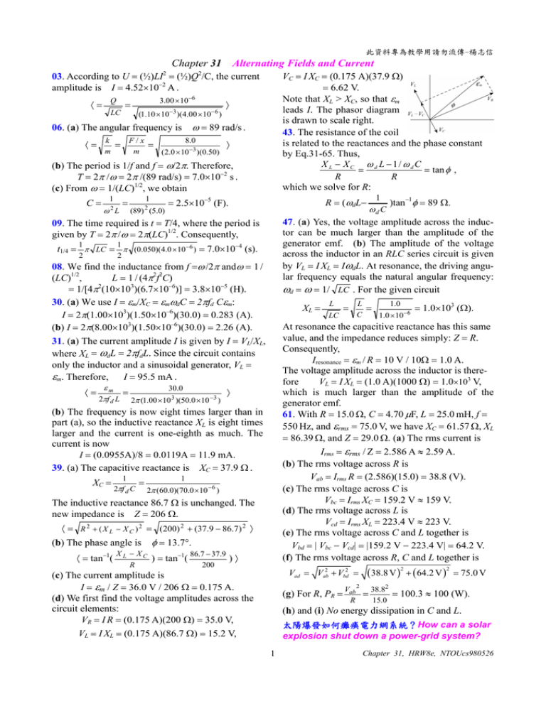
此資料專為教學用請勿流傳-楊志信 Chapter 31 Alternating Fields and Current 03. According to U = (½)LI2 = (½)Q2/C, the current amplitude is I = 4.52×10⁻² A . ⟨= Q 3.00 × 10−6 = (1.10 × 10⁻³ )(4.00 × 10⁻⁶ ) LC k m F/x m = = ⟩ ω = 89 rad/s . 06. (a) The angular frequency is ⟨= VC = I XC = (0.175 A)(37.9 Ω) = 6.62 V. Note that XL > XC, so that εm leads I. The phasor diagram is drawn to scale right. 43. The resistance of the coil is related to the reactances and the phase constant by Eq.31-65. Thus, X L − XC ω d L −1/ ω dC = = tan φ , R R which we solve for R: 8.0 (2.0 × 10⁻³ )(0.50) ⟩ (b) The period is 1/f and f = ω/2π. Therefore, T = 2π /ω = 2π /(89 rad/s) = 7.0×10⁻² s . (c) From ω = 1/(LC)1/2, we obtain C= 1 ω L 2 2 (89) (5.0) 09. The time required is t = T/4, where the period is given by T = 2π /ω = 2π(LC)1/2. Consequently, 47. (a) Yes, the voltage amplitude across the inductor can be much larger than the amplitude of the generator emf. (b) The amplitude of the voltage across the inductor in an RLC series circuit is given by VL = I XL = IωdL. At resonance, the driving angular frequency equals the natural angular frequency: ωd = ω = 1/ LC . For the given circuit t1/4 = π LC = π (0.050)(4.0 × 10⁻⁶ ) = 7.0×10⁻⁴ (s). 1 2 1 2 08. We find the inductance from f =ω /2π andω = 1 / (LC)1/2, L = 1 / (4π2f2C) 2 = 1/[4π (10×103)(6.7×10⁻⁶)] = 3.8×10⁻⁵ (H). 30. (a) We use I = εm/XC = εmωdC = 2πfd Cεm: I = 2π(1.00×10³)(1.50×10⁻⁶)(30.0) = 0.283 (A). (b) I = 2π(8.00×10³)(1.50×10⁻⁶)(30.0) = 2.26 (A). 31. (a) The current amplitude I is given by I = VL/XL, where XL = ωdL = 2πfdL. Since the circuit contains only the inductor and a sinusoidal generator, VL = εm. Therefore, I = 95.5 mA . ⟨= εm 2πf d L = 30.0 2π (1.00 ×10 3 )(50.0 ×10 −3 ) XL = 1 2πf d C = ⟩ 1 2π (60.0)(70.0 × 10 −6 ) The inductive reactance 86.7 Ω is unchanged. The new impedance is Z = 206 Ω. ⟨ = R 2 + ( X L − X C ) 2 = (200) 2 + (37.9 − 86.7) 2 ⟩ (b) The phase angle is ⟨ = tan−1( X L − XC R φ = 13.7°. ) = tan−1( 86.7 − 37.9 200 L LC = L C = 1.0 1.0 × 10−6 = 1.0×10³ (Ω). At resonance the capacitive reactance has this same value, and the impedance reduces simply: Z = R. Consequently, Iresonance = εm / R = 10 V / 10Ω = 1.0 A. The voltage amplitude across the inductor is therefore VL = I XL = (1.0 A)(1000 Ω) = 1.0×10³ V, which is much larger than the amplitude of the generator emf. 61. With R = 15.0 Ω, C = 4.70 μF, L = 25.0 mH, f = 550 Hz, and εrms = 75.0 V, we have XC = 61.57 Ω, XL = 86.39 Ω, and Z = 29.0 Ω. (a) The rms current is Irms = εrms / Z = 2.586 A ≈ 2.59 A. (b) The rms voltage across R is Vab = Irms R = (2.586)(15.0) = 38.8 (V). (c) The rms voltage across C is Vbc = Irms XC = 159.2 V ≈ 159 V. (d) The rms voltage across L is Vcd = Irms XL = 223.4 V ≈ 223 V. (e) The rms voltage across C and L together is Vbd = | Vbc − Vcd| = |159.2 V − 223.4 V| = 64.2 V. (f) The rms voltage across R, C and L together is (b) The frequency is now eight times larger than in part (a), so the inductive reactance XL is eight times larger and the current is one-eighth as much. The current is now I = (0.0955A)/8 = 0.0119A = 11.9 mA. 39. (a) The capacitive reactance is XC = 37.9 Ω . XC = 1 )tan−1φ = 89 Ω. ωd C R = (ωdL− = 2.5×10⁻⁵ (F). 1 = )⟩ Vad = Vab2 + Vbd2 = (c) The current amplitude is I = εm / Z = 36.0 V / 206 Ω = 0.175 A. (d) We first find the voltage amplitudes across the circuit elements: VR = I R = (0.175 A)(200 Ω) = 35.0 V, VL = I XL = (0.175 A)(86.7 Ω) = 15.2 V, (g) For R, PR = Vab 2 R ( 38.8 V ) + ( 64.2 V ) 2 = 38.82 15.0 2 = 75.0 V = 100.3 ≈ 100 (W). (h) and (i) No energy dissipation in C and L. 太陽爆發如何癱瘓電力網系統?How can a solar explosion shut down a power-grid system? 1 Chapter 31, HRW8e, NTOUcs980526

