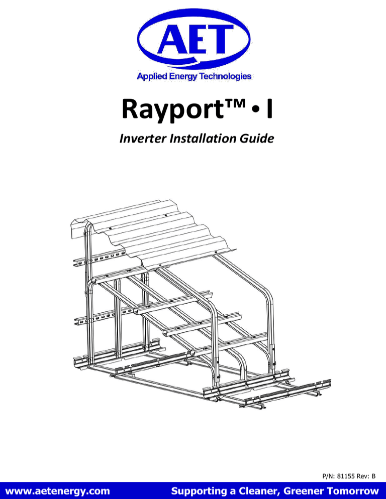
Installation Guide
advertisement

Rayport™ • I Inverter Installation Guide P/N: 81155 Rev: B www.aetenergy.com Supporting a Cleaner, Greener Tomorrow 1. Table of Contents 1. Table of Contents 2. Installer Notes 3. Parts List 4. Tool List 5. Assembly 6. Appendix A: Inverter Accessory Mounting Kit 7. Appendix B: Canopy Kit 8. Appendix C: Load Center Kit P2 P/N: 81155 Rev: B P2 P3 P3 P4 P5-11 P12-13 P14-19 P20-22 2. Installer Notes Thank you for purchasing AET’s Rayport™ • I Inverter Mounting Kit that is manufactured in Maumee, Ohio. This kit has been designed to mount string inverters at a 20 degree angle. Note: This installation guide must be read in its entirety prior to installation. Note: Documented inspection, maintenance, cleaning and adjustments are required annually to maintain product warranty. 3. Parts List Support Rail - 20 degree angle Ballast Tray Assembly Brace – Cross Rail Screw - ¼” - 20 x 3/4” Flange Hex w/ lock patch Washer Screw - ¼” inner diameter Washer - 5/ ” 16 Spring Nut inner diameter Unistrut -Perma Green Acrylic Coating P3 - 5/16” - 18 x 1” Hex - 5/16” - 18 Unistrut Spring Nut Sliding Retainer Nut P/N: 81155 Rev: B 4. Tool List 3/ ” 8 Socket w/ Ratchet or Impact Driver ½” Socket w/ Ratchet Torque Wrench 5/ ”Drill 16 3/ ” 8 P4 Bit Drill P/N: 81155 Rev: B 5. Assembly 1. Support Rail to Ballast Tray Assembly Assemble (2) ballast trays to (3) support rails using (6) ¼” screws and sliding retainer nuts. See figures 1a, 1b and 1c. Torque to 50-60 in-lb. Note: Ballast trays can be positioned under the support rails. See figure 1d. Refer to Appendix C is installing a Load Center Kit. Attach support rails to the center 3 notch positions. Figure 1a ¼” – 20 Screw Sliding Retainer Nut Figure 1b P5 P/N: 81155 Rev: B 5. Assembly - Continued Torque to 50-60 in-lb. (6) places. Figure 1c Figure 1d P6 P/N: 81155 Rev: B 5. Assembly - Continued 2. Attach Upper Unistrut to Support Rail Assembly Attach the upper unistrut to the support rail assembly using (3) ¼”screws, washers and sliding retainer nuts. (See figure 2a & 2b) ¼” Screw and Washer Sliding Retainer Nut Figure 2a Torque to 50-60 in-lb. (3) places. Figure 2b P7 P/N: 81155 Rev: B 5. Assembly - Continued 3. Brace to Support Rail Assembly Note: Skip this step if installing the Load Center Kit. Reference Appendix C. Loosely attach one end of the brace to the support rail using (1) ¼” screw, washer and sliding retainer nut. (See figure 3a). Rotate the loose end of the brace until the hex hole is centered on the side of the support rail. Drill a hole into the support rail using a 5/16” drill bit. Attach this end of the brace to the support rail using (1) ¼” screw, washer and sliding retainer nut. (See figure 3b, 3c and 3d). ¼” Screw and Washer Sliding Retainer Nut Figure 3a Support Rail Attached End Brace Figure 3b Figure 3c P8 P/N: 81155 Rev: B 5. Assembly - Continued 4. Brace to Support Rail Assembly - Continued Drill a hole thru both the brace midpoint and the center support rail using a 5/16” drill bit. Attach the center of the brace to the support rail using (1) ¼” screw, washer and sliding retainer nut. (See figures 3e, 3f and 3g). Sliding Retainer Nut Torque the brace fasteners to 50-60 in-lb. ¼” Screw and Washer Brace Midpoint Figure 3d Sliding Retainer Nut Figure 3e Figure 3f ¼” Screw and Washer Figure 3g Torque to 50-60 in-lb. P9 P/N: 81155 Rev: B 5. Assembly - Continued 5. Attach Lower Unistrut to Support Rail Assembly Attach the lower unistrut to the support rail assembly using (3) ¼” screws, washers and sliding retainer nuts. Holes must be drilled into the support rails using a 5/16” drill bit prior to mounting the unistrut. Note: Reference the inverter installation guide for the correct hole spacing. (See figure 5a). Torque all fasteners to 50-60 in-lb. Mount the inverter to the unistrut per the inverter installation guide. Use the provided 5/16” screws and spring nuts. Note: The maximum allowable weight of the inverter is 250 lbs. ¼” Screw and Washer Sliding Retainer Nut Figure 5a P10 P/N: 81155 Rev: B 5. Assembly - Continued 6. Ballast Requirements Add ballast to the ballast trays or use anchors to attach the inverter rack to the roof. See Figure 6 for ballast and anchor requirements. Figure 6 P11 P/N: 81155 Rev: B 6. Appendix A – Inverter Accessory Mounting Kit 7. Installer Notes Thank you for purchasing AET’s Rayport™ • I Inverter Accessory Mounting Kit that is manufactured in Maumee, Ohio. This kit is designed to allow inverter accessories to be mounted to the Rayport™ • I racking system. 8. Parts List Unistrut Screw - 5/16” - 18 x 1” Hex - Perma Green Acrylic Coating Spring Nut Washer - 5/16” - 18 Unistrut Spring Nut - 5/16” Flat Sliding Retainer Nut Screw - ¼” - 20 x 3/4” Flange Hex w/ lock patch Washer - ¼” inner diameter 9. Tool List 3/ ” 8 Socket w/ Ratchet or Impact Driver ½” Socket w/ Ratchet or Impact Driver Torque Wrench P12 P/N: 81155 Rev: B 6. Appendix A – Inverter Accessory Mounting Kit – Continued 10. Assembly Attach the unistrut to the support rails using (6) ¼” screws, washers and sliding retainer nuts. Holes must be drilled into the support rails using a 5/16” drill bit prior to mounting the unistrut. Note: Review the accessory installation manual to determine the correct hole spacing. Also, the cross brace must be removed if the accessory kit is mounted on the vertical legs. See figures 10a, 10b and 10c. ¼” Screw And Washer Sliding Retainer Nut Torque the fasteners to 50-60 in-lb. Mount the accessory to the unistrut per the accessory installation manual. Use the provided 5/16” screws and spring nuts. Note: The combined maximum allowable weight of the inverter and accessory is 250lbs. The maximum allowable weight of the accessory, if mounted on the vertical legs, is 50 lbs. Reference section 6 on page 11 for ballast requirements. Figure 10a Optional location for accessory mounting kit Figure 10b Cross Brace Vertical Leg Figure 10c P13 P/N: 81155 Rev: B 7. Appendix B – Canopy Kit 11. Installer Notes Thank you for purchasing AET’s Rayport™ • I Canopy Kit that is manufactured in Maumee, Ohio. This kit is designed to shade a string inverter when mounted to the Rayport™ • I racking system. 12. Parts List Support Rail - Canopy Canopy - 20 degree support rail. Bracket Screw - Canopy Support - ¼” - 20 Flange Hex with lock patch Washer Sliding Retainer Nut - ¼” inner diameter 13. Tool List 3/ ” 8 Socket w/ Ratchet or Impact Driver Torque Wrench P14 P/N: 81155 Rev: B 7. Appendix B – Canopy Kit Assembly 14. Canopy Bracket to Support Rail Assembly Attach the canopy brackets to the support rails using (4) ¼” screws. Torque the fasteners to 50-60 in-lbs. (See figures 14a and 14b). Canopy Support Rails ¼” bolt Canopy Support Brackets Canopy Support Brackets Figure 14a Torque to 50-60 in-lb. Torque to 50-60 in-lb. Figure 14b P15 P/N: 81155 Rev: B 7. Appendix B – Canopy Kit Assembly – Continued 15. Canopy Bracket/Support Rail to Rayport I Assembly Loosely attach the canopy bracket/support rail assembly’s to the rear legs of the Rayport I system using (2) ¼” screws and sliding retainer nuts. Use the existing thru holes in the rear legs of the Rayport I support rail. (See figure 15a, 15b and 15c). Existing thru hole in rear leg Figure 15a Figure 15b Thru hole location Rear Legs Figure 15c P16 P/N: 81155 Rev: B 7. Appendix B – Canopy Kit Assembly – Continued 16. Canopy Bracket/Support Rail to Rayport I Assembly - Continued Position the loose end of the canopy bracket/support rail assembly’s onto the front legs of the Rayport I system. Assemble the canopy bracket/support rail assembly’s to the front legs using (2) ¼” screws and sliding retainer nuts. (See figure 16a & 16b). Torque all canopy bracket fasteners to 50-60 in-lb. (See figure 16c). Existing thru hole in front leg. Canopy Support Rail Figure 16a ¼” Screw Sliding Retainer Nut Figure 16b Torque to 50-60 in-lb. Torque to 50-60 in-lb. Figure 16c P17 P/N: 81155 Rev: B 7. Appendix B – Canopy Kit Assembly – Continued 17. Canopy Assembly Thru holes (6) places Position the canopy on the canopy support rails so that the (4) riv nuts line up with (4) of the holes in the canopy. Loosely attach the canopy using (4) ¼” screws and washers. See figures 17a and 17b. Rotate the canopy along the radius of the canopy support rails until the last set of holes line up with the holes just below the radius. Attach the canopy to the support rails using (2) ¼” screws, washers and sliding retainer nuts. See figures 17c. Torque to 50-60 in-lbs. Existing hole just below radius Riv Nuts ¼” screws and washers Figure 17a Figure 17b ¼” screws and washers Sliding Retainer Nut Figure 17c P18 P/N: 81155 Rev: B 7. Appendix B – Canopy Kit Assembly – Continued 18. Ballast Requirements Add ballast to the ballast trays or use anchors to attach the inverter rack to the roof. See Figure 18 for ballast and anchor requirements. Figure 18 P19 P/N: 81155 Rev: B 8. Appendix C – Load Center Kit 19. Installer Notes Thank you for purchasing AET’s Rayport I Load Center Kit that is manufactured in Maumee, Ohio. This kit is designed to mount a load center to the Rayport I system. Note: A Canopy Cover Kit must be installed prior to installing the Load Center Kit. 20. Parts List Unistrut Screw - 5/16” - 18 x 1” Hex - Perma Green Acrylic Coating Spring Nut Washer - 5/16” - 18 Unistrut Spring Nut - 5/16” Flat Sliding Retainer Nut Screw - ¼” - 20 x 3/4” Flange Hex w/ lock patch Washer Bridge Assembly - ¼” inner diameter 21. Tool List 3/ ” 8 Socket w/ Ratchet or Impact Driver ½” Socket w/ Ratchet 3/ ” 8 Torque Wrench P20 5/ ” 16 P/N: 81155 Rev: B Drill Bit Drill 8. Appendix B – Load Center Kit Assembly 22. Ballast Tray Placement If needed, re-position the ballast trays as shown in figure 21a. 23. Bridge Rail to Ballast Tray Assembly Attach (2) bridge rails to the ballast trays using (4) ¼” screws. Torque to 50-60 in lb. See figures 22a, 22b and 22c. Figure 21a ¼” Screw Position Bridge Rail in Ballast Tray notch Figure 22b Figure 22a Figure 22c P21 Torque to 50-60 in-lb (4) places P/N: 81155 Rev: B Bridge Rail 8. Appendix B – Load Center Kit Assembly – Continued 24. Cross Brace If needed, remove the cross brace from the vertical legs of the inverter rack. See figure 23a. Remove Cross Rail 25. Unistrut Attachment Figure 23a Attach the unistrut to the support rails using (4) ¼” screws, washers and sliding retainer nuts. Holes must be drilled into the support rails using a 5/16” drill bit prior to mounting the unistrut. Note: Review the load center installation manual to determine the correct hole spacing. See figures 24a. Torque the fasteners to 50-60 in-lb. Mount the load center to the unistrut per the load center installation manual. Use the provided 5/16” screws and spring nuts. Note: The maximum allowable weight of the load center is 250 lbs. Reference section 18 on page 19 for ballast requirements. Sliding Retainer Nut (4) Places ¼” Screw and Washer (4) Places Figure 24a P22 P/N: 81155 Rev: B

