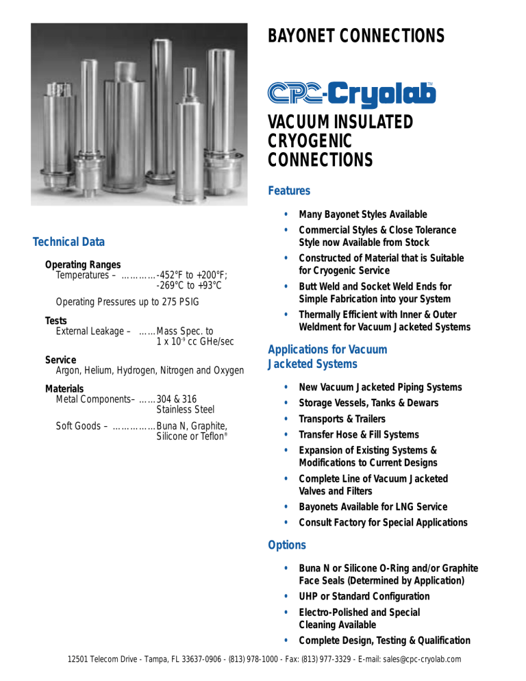
Bayonet Connections - CPC

BAYONET CONNECTIONS
TM
VACUUM INSULATED
CRYOGENIC
CONNECTIONS
Features
Technical Data
Operating Ranges
Temperatures – …………-452°F to +200°F;
-269°C to +93°C
Operating Pressures up to 275 PSIG
Tests
External Leakage – ……Mass Spec. to
1 x 10 -9 cc GHe/sec
Service
Argon, Helium, Hydrogen, Nitrogen and Oxygen
Materials
Metal Components– ……304 & 316
Stainless Steel
Soft Goods – ……………Buna N, Graphite,
Silicone or Teflon ®
• Many Bayonet Styles Available
• Commercial Styles & Close Tolerance
Style now Available from Stock
• Constructed of Material that is Suitable for Cryogenic Service
• Butt Weld and Socket Weld Ends for
Simple Fabrication into your System
• Thermally Efficient with Inner & Outer
Weldment for Vacuum Jacketed Systems
Applications for Vacuum
Jacketed Systems
• New Vacuum Jacketed Piping Systems
• Storage Vessels, Tanks & Dewars
• Transports & Trailers
• Transfer Hose & Fill Systems
• Expansion of Existing Systems &
Modifications to Current Designs
• Complete Line of Vacuum Jacketed
Valves and Filters
• Bayonets Available for LNG Service
• Consult Factory for Special Applications
Options
• Buna N or Silicone O-Ring and/or Graphite
Face Seals (Determined by Application)
• UHP or Standard Configuration
• Electro-Polished and Special
Cleaning Available
• Complete Design, Testing & Qualification
12501 Telecom Drive - Tampa, FL 33637-0906 - (813) 978-1000 - Fax: (813) 977-3329 - E-mail: sales@cpc-cryolab.com
BAYONET CONNECTIONS
Commercial Bayonets Vacuum Jacketed for Hydrogen & Helium
For Hoses, Tankers and Storage Vessels
C D
A
B
E
MALE AIR FORCE HYDROGEN SERVICE *
Size P\N A B C D E
1-1/2” PS F-BMAFPS12X 10.6” 9.6” 3.5” 1.9” 7.0”
1-1/2” ODT F-BMAFTS12X
Temp. -423°F MAWP 200 PSIG
10.6” 9.6” 3.5” 1.5” 7.0”
Inner Line
1-1/2” Sch. 5 Pipe
1-1/2” x .065” Tube
*Shipped with nose seal and o-ring.
G
H I
FEMALE AIR FORCE HYDROGEN SERVICE
Size
1-1/2” PS
P\N
F-BFAFPS12X
F G H I
Temp. -423°F MAWP 200 PSIG
J
10.0” 4.0” 3.5” 1.9” 7.2”
Inner Line
1-1/2” Sch. 5 Pipe
1-1/2” ODT F-BFAFTS12X
1” PS F-BFAFPS08X
1” ODT F-BFAFTS08X
10.0” 4.0”
10.0” 4.0”
10.0” 4.0”
3.5”
3.5”
3.5”
1.5”
1.3”
1.0”
7.2”
7.2”
7.2”
1-1/2” x .065” Tube
1” Sch. 5 Pipe
1” x .065” Tube
F
J
B
A
E
C D
MALE LINDE TYPE HYDROGEN SERVICE*
Size
2” ODT
P\N
F-BMLTTS16X
1-1/2” ODT F-BMLTTS12X
A
8.8”
8.8”
B
8.2”
8.2”
C
3.5”
3.5”
D
2.0”
1.5”
Temp. -423°F MAWP 200 PSIG
E
6.8”
6.8”
Inner Line
2” x .065” Tube
1-1/2” x .065” Tube
*Shipped with nose seal and energizer. V-Band Clamp required for installation.
G
H I
J
FEMALE LINDE TYPE HYDROGEN SERVICE*
Size
2” PS
P\N
F-BFLTPS16X
F G H I
Temp. -423°F MAWP 200 PSIG
J
13.0” 8.1” 3.5” 2.38” 8.6”
Inner Line
2” Sch. 5 Pipe
2” ODT F-BFLTTS16X
1-1/2” PS F-BFLTPS12X
13.0” 8.1”
13.0” 8.1”
3.5”
3.5”
2.00” 8.6”
1.30” 8.6”
1-1/2” ODT F-BFLTTS12X 13.0” 8.1” 3.5” 1.00” 8.6”
*Shipped with Kel-F o-ringr. V-Band Clamp required for installation.
2” x .065” Tube
1-1/2” Sch. 5 Pipe
1-1/2” x .065” Tube
F
A
B
C D
MALE HELIUM SERVICE*
Size
2” ODT
P\N A B C D
Temp. -452°F MAWP 175 PSIG
E Inner Line
F-BMCYTS16X 17.5” 16.5” 3.5” 2.0” 15.0” 2” x .065” Tube
*Shipped with nose seal and o-ring. V-Band Clamp required for installation.
E
G
H I
FEMALE HELIUM SERVICE*
Size
2” ODT
P\N
F-BFCYTS16X
*V-Band Clamp required for installation.
Temp. -452°F MAWP 175 PSIG
F G H I J Inner Line
17.38”15.38” 3.5” 2.0” 14.7” 2” x .065” Tube
F
J
Dimensions are shown for reference only.
V-BAND CLAMP
Model
Linde Type w/Handwheel
P\N
F-1575
Helium Service w/Handwheel F1585
Helium Service F1600
– 37 –
BAYONET CONNECTIONS
Commercial Bayonets – Assembly Kits & Options
AIR FORCE TYPE BAYONETS *
Description
Kit:
O-Ring
Nose Seal
Optional:
Dust Cap
Pressure Cap, Female
Material
Buna N
TFE
P/N F-BPAFxxxx K
Aluminum
Stainless Steel
Letter
O
N
D
S
*The Air Force Type Bayonet is a threaded connection which uses a Teflon ® nose seal and Buna N O-ring on the male Bayonet. An assembly kit is required for each pair.
LINDE TYPE BAYONET*
Description
Kit:
O-Ring
Energizer
Nose Seal
Optional:
Dust Cap
Pressure Cap, Female
Material
PCTFE
TFE
P/N F-BPLTxxxx K
Stainless Steel
Aluminum
Stainless Steel
Letter
O
E
N
D
S
*The Linde Type Bayonet is a V-band connection which uses a Teflon ® nose seal and an energizer on the male Bayonet and a Kel-F O-ring on the female Bayonet. An assembly kit is required for each pair and a V-Band Clamp is required for installation.
Spare Assembly Kits
Type
Air Force
Linde
Helium
Part Number
F-B P AFxxxx K
F-B P LTxxxx K
F-B P CYxxxx K
Sample Kit Number:
F–B P CYxxxx K
When ordering parts for male and female
Bayonets change the “P” in the Kit
Number above to the identification letter for the connection type shown below:
P = Pair
M = Male
F = Female
To order Optional or Kit Items change the
“K” at the end of the Kit Number above to the identification letter for the kit description as shown below:
O = O-Ring
N = Nose Seal
E = Energizer for Linde Type
Nose Seal
K = Complete Assembly Kits as described above
D = Aluminum Dust Cap
S = Stainless Steel Pressure Cap HELIUM SERVICE BAYONET*
Description
Kit:
O-Ring
Nose Seal
Optional:
Dust Cap
Pressure Cap, Female
Material
Buna N
TFE
P/N F-BPCYxxxx K
Aluminum
Stainless Steel
Letter
O
N
D
S
*The Helium Bayonet is a V-band connection which uses a Teflon ® nose seal and Buna
N O-ring on the male Bayonet. An assembly kit is required for each pair and a V-Band
Clamp is required for installation.
12501 Telecom Drive - Tampa, FL 33637-0906 - (813) 978-1000 - Fax: (813) 977-3329 - E-mail: sales@cpc-cryolab.com
BAYONET CONNECTIONS
Close Tolerance Bayonets, Dual Seal
For Fixed Vacuum Jacketed Piping Systems
Specify Service: Standard, Oxygen or Hydrogen
F B A
E
G
D
ANSI Class 150# Flange Typical
C
Spare Assembly Kits
Size
1/2” x 2”
1” x 2-1/2”
1-1/2” x 3”
2” x 4”
3” x 5”
4” x 6”
6” x 10”
Kit Number
F-BPCTPS04K
F-BPCTPS08K
F-BPCTPS12K
F-BPCTPS16K
F-BPCTPS24K
F-BPCTPS32K
F-BPCTPS48K
Sample Kit Number:
MALE CLOSE TOLERANCE*
Size* P\N
1/2” x 2” F-BMCTPS04X
1” x 2-1/2” F-BMCTPS08X
1-1/2” x 3” F-BMCTPS12X
2” x 4” F-BMCTPS16X
3” x 5”
4” x 6”
F-BMCTPS24X
F-BMCTPS32X
6” x 10” F-BMCTPS48X
Temp. -423°F MAWP 275 PSIG
A B C D E F G
∆
Q
0.84” 2.37” 1.56” 8” 12” 6.0” 11” 4.5
1.31” 2.87” 1.75” 10” 14” 7.0” 13” 4.9
1.90” 3.50” 2.44” 9” 13” 7.5” 12” 9.1
2.37” 4.50” 2.94” 11” 15” 9.0” 14” 9.7
3.50” 5.56” 3.92” 12” 16” 10.0” 15” 10.5
4.50” 6.62” 5.35” 16” 20” 11.0” 19” 19.2
6.62” 10.75” 8.39” 18” 22” 16.0” 21” 41.0
* Male bayonet shipped with all assembly hardware and seals.
L
J
K
SI Type Insulation
H I
F–BPCTP S 12 K for 1-1/2” x 3” Bayonet Pair
Required Assembly Parts For Close
Tolerance Bayonets:
To order individual components from
Assembly Kits change the “K” at the end of the Kit Number above to the I.D. letter for the component as shown below:
O = O-Ring for Face Seal
N = Nose Seal Only
H = Nuts & Bolts to assemble Male and
Female Bayonet
K = Nose Seal, O-Rings and Nuts & Bolts
Specify Service:
To specify service other than Standard, change the “S” in the Part Number shown above to the I.D. letter for the service shown below:
S = Standard Service includes Argon,
Helium and Liquid Nitrogen
O = Oxygen Service, Consult Factory
H = Hydrogen Service, Consult Factory
FEMALE CLOSE TOLERANCE
Size* P\N
1/2” x 2” F-BFCTPS04X
1” x 2-1/2” F-BFCTPS08X
1-1/2” x 3” F-BFCTPS12X
2” x 4” F-BFCTPS16X
3” x 5”
4” x 6”
F-BFCTPS24X
F-BFCTPS32X
6” x 10” F-BFCTPS48X
Temp. -423°F MAWP 275 PSIG
H I J K L
∆
Q
0.84” 2.37” 9.00” 11.00” 2.94” 6.7
1.31” 2.87” 11.38” 13.38” 3.88” 7.9
1.90” 3.50” 10.38” 12.38” 4.00” 6.5
2.37” 4.50” 11.63” 13.63” 5.00” 6.0
3.50” 5.56” 13.75” 15.75” 6.49” 14.7
4.50” 6.62” 18.00” 20.00” 7.94” 31.7
6.62” 10.75” 19.25” 21.25” 11.94” 37.0
The close tolerance Dual Seal Bayonet is a flanged connection using ANSI type flanges. It is assembled with two O-rings, Teflon® nose seal and stainless steel nuts and bolts. An assembly kit is required for each pair.
Notes for Close Tolerance Bayonets:
SI – Sixteen layers of laminar radiation shielding consisting of alternating layers of glass paper and aluminum foil.
∆
Q – Conductive heat leak from ambient to cryogenic temperature. BTU/Hr. @ 77.4°K (LN2).
* – Nominal pipe size. All pipe is Schedule 5 unless noted.
Dimensions shown above are for reference only.
12501 Telecom Drive - Tampa, FL 33637-0906 - (813) 978-1000 - Fax: (813) 977-3329 - E-mail: sales@cpc-cryolab.com


