Line Trap
advertisement
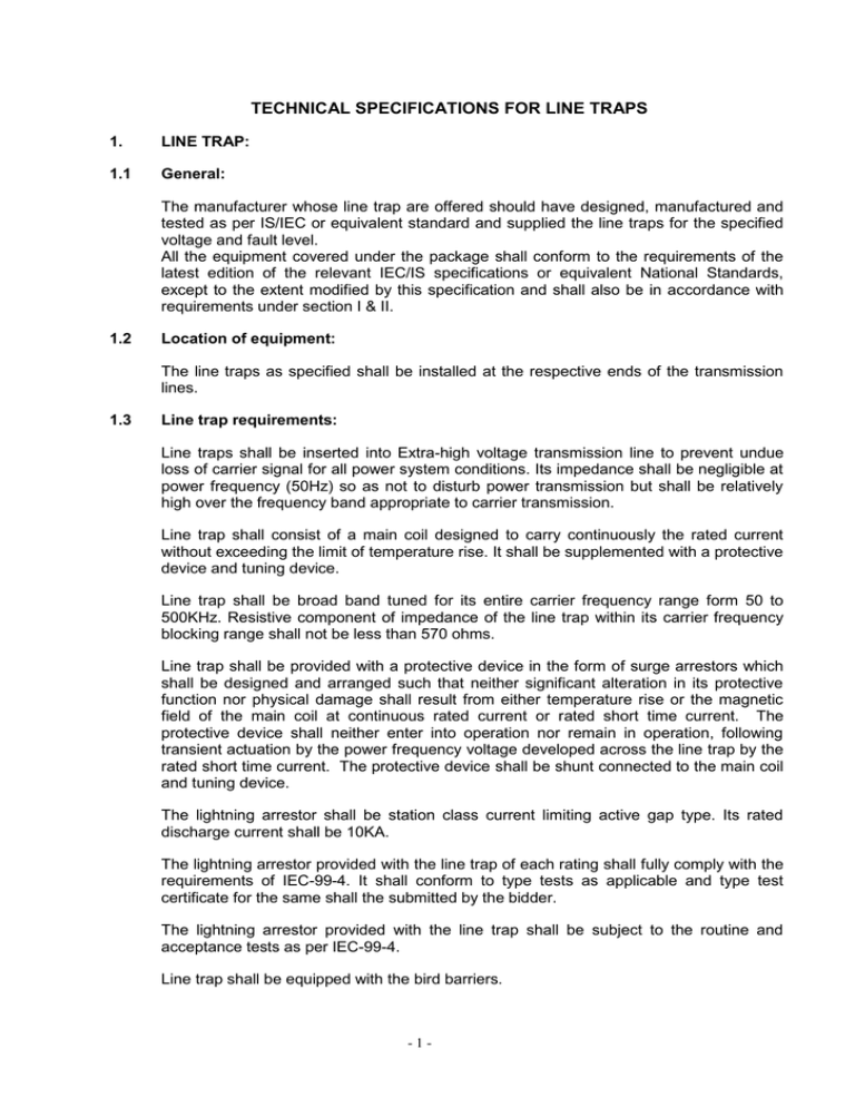
TECHNICAL SPECIFICATIONS FOR LINE TRAPS 1. LINE TRAP: 1.1 General: The manufacturer whose line trap are offered should have designed, manufactured and tested as per IS/IEC or equivalent standard and supplied the line traps for the specified voltage and fault level. All the equipment covered under the package shall conform to the requirements of the latest edition of the relevant IEC/IS specifications or equivalent National Standards, except to the extent modified by this specification and shall also be in accordance with requirements under section I & II. 1.2 Location of equipment: The line traps as specified shall be installed at the respective ends of the transmission lines. 1.3 Line trap requirements: Line traps shall be inserted into Extra-high voltage transmission line to prevent undue loss of carrier signal for all power system conditions. Its impedance shall be negligible at power frequency (50Hz) so as not to disturb power transmission but shall be relatively high over the frequency band appropriate to carrier transmission. Line trap shall consist of a main coil designed to carry continuously the rated current without exceeding the limit of temperature rise. It shall be supplemented with a protective device and tuning device. Line trap shall be broad band tuned for its entire carrier frequency range form 50 to 500KHz. Resistive component of impedance of the line trap within its carrier frequency blocking range shall not be less than 570 ohms. Line trap shall be provided with a protective device in the form of surge arrestors which shall be designed and arranged such that neither significant alteration in its protective function nor physical damage shall result from either temperature rise or the magnetic field of the main coil at continuous rated current or rated short time current. The protective device shall neither enter into operation nor remain in operation, following transient actuation by the power frequency voltage developed across the line trap by the rated short time current. The protective device shall be shunt connected to the main coil and tuning device. The lightning arrestor shall be station class current limiting active gap type. Its rated discharge current shall be 10KA. The lightning arrestor provided with the line trap of each rating shall fully comply with the requirements of IEC-99-4. It shall conform to type tests as applicable and type test certificate for the same shall the submitted by the bidder. The lightning arrestor provided with the line trap shall be subject to the routine and acceptance tests as per IEC-99-4. Line trap shall be equipped with the bird barriers. -1- Line trap shall conform to IEC-353 (latest) fulfilling the all technical requirements as follows: Technical Parameter 220kV line 66kV line Rated power frequency 50 Hz 50 Hz Rated system voltage 220kV 66kV Highest system voltage 245kV 72.5kV Rated continuous, current at 50 degree C ambient. 1250A 630A 31.5KA ---------- 16KA Broad band to be indicated by bidder --------- ______ 1.0 1.0 Rated short time current for 1 second Type of tuning Rated blocking band-width Minimum resistive component of impedance within the rated blocking band-width Rated inductance of main coil (mH) Radio interference voltage Not more than 500 micro volt at 187 kV (rms) The Bidder shall indicate continuous current rating of the line trap at 65 deg. C ambient. The line trap shall conform in type tests and shall be subjected to routine tests as per IEC-353, as per following details: TYPE TEST: The equipment should be offered type test. Test reports should not more then seven years old reckoned from date of bid opening in respect of all the tests carried out in accredited laboratories (based on ISO/IEC) by a reputed accreditatic body or witnessed by HVPN or another electric power utility and be submitted by the successful bidder to HVPNL for approval as schedule given in Bar Chart. i) Short time current test. ii) iii) iv) v) vi) vii) viii) ix) x) Power frequency voltage test on tuning device. Impulse voltage test. Temperature rise test Measurement of radio influence voltage Measurement of the rated inductance of the main coil Measurement of power frequency inductance of the mail coil Measurement of blocking resistance and blocking impedance Measurement of tapping loss and tapping loss based on the blocking resistance Measurement of loss at power frequency. Routine Test: As per quality assurance program (QAP). ACCEPTANCE TESTS: The following acceptance tests as stipulated in the relevant IS-8793: 1995 shall be carried out by the Supplier in presence of HVPNL representative, unless dispensed with in writing by the HVPNL. -2- i) ii) iii) iv) 1.4 Power frequency voltage test on tuning device. Measurement of the rated inductance of the main coil Measurement of blocking resistance and blocking impedance Measurement of tapping loss and tapping loss based on the blocking resistance LINE TRAP MOUNTING: The line trap shall be suitable for outdoor suspension mounting and shall be mechanically strong enough to withstand the stresses due to maximum wind pressure of 260kg/Square meter. Contractor shall be required to co-ordinate the mounting arrangement with the existing arrangement at different sub-stations. Non-magnetic suspension hook/link of adequate length and tensile strength to provide necessary magnetic clearance between the line trap and suspension hardware shall be supplied by the Contractor. The line trap shall be supplied compete with disc insulators and hardware fittings. The disc insulators to be supplied with the line trap shall conform to IS: 731/1971 with latest amendments. All hardware fittings associated with these insulators shall conform to IS: 2486 (Part-I)/1971 (1st Revision), IS: 2486 (Part-II)/1971 (1st Revision), IS:2486 (PartIII)/1974 and IS:2486 (Part-IV)/1981 with latest amendments & revision. Copies of test certificates of type tests and routine tests as stipulated in the above quoted ISS shall be furnished with tender. 1.5 LINE TRAP TERMINAL CONNECTORS: The line traps shall be suitable for connecting to ACSR single/twin bundle Zebra conductor as per layout requirements. Necessary connector shall be supplied by the Contractor. Terminal connectors shall conform to IS: 5561 and shall also comply with requirements indicated in Section GTR. Terminal connectors shall be suitable for either horizontal or vertical take off the conductor. 1.6 Clamps/connectors shall be designed for the same current ratings as line trap and temperature rise shall not exceed 0.5 deg.C over 50 deg C ambient. DOCUMENTATION The successful bidder shall submit four sets of following drawings for HVPNL approval:- NOTE: 1. Outline general arrangement 2. Name and rating plate 3. line trap mounting arrangement 4. terminal connectors 5. Any other drawing required to complete the equipment like bird barrier etc. All above drawings should be a minimum space (14x10cm) for stamping the approval of drawings by HVPNL. -3-


