bistable multivibrator - benchmark
advertisement

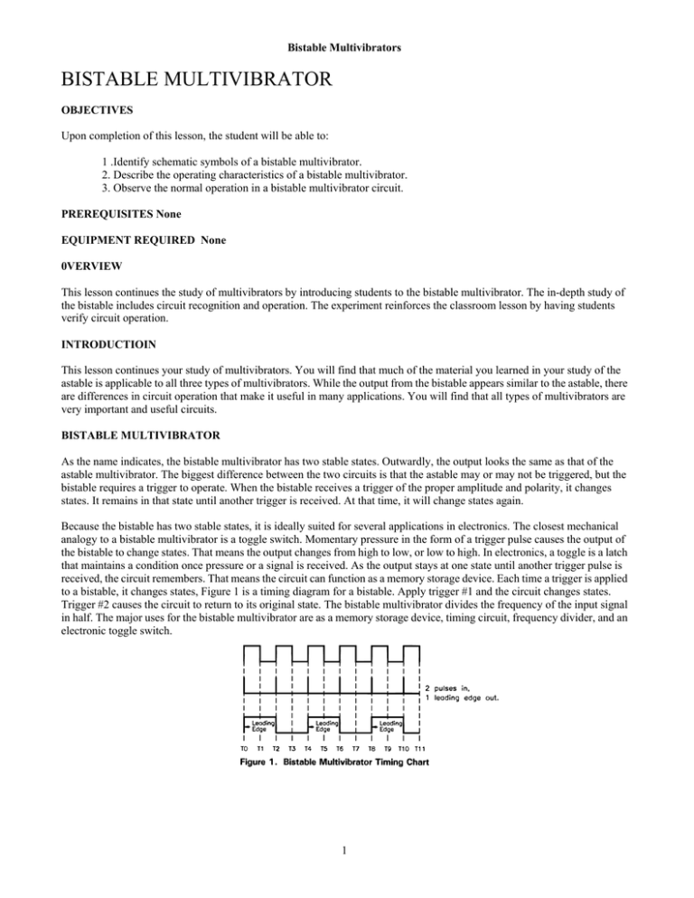
Bistable Multivibrators BISTABLE MULTIVIBRATOR OBJECTIVES Upon completion of this lesson, the student will be able to: 1 .Identify schematic symbols of a bistable multivibrator. 2. Describe the operating characteristics of a bistable multivibrator. 3. Observe the normal operation in a bistable multivibrator circuit. PREREQUISITES None EQUIPMENT REQUIRED None 0VERVIEW This lesson continues the study of multivibrators by introducing students to the bistable multivibrator. The in-depth study of the bistable includes circuit recognition and operation. The experiment reinforces the classroom lesson by having students verify circuit operation. INTRODUCTIOIN This lesson continues your study of multivibrators. You will find that much of the material you learned in your study of the astable is applicable to all three types of multivibrators. While the output from the bistable appears similar to the astable, there are differences in circuit operation that make it useful in many applications. You will find that all types of multivibrators are very important and useful circuits. BISTABLE MULTIVIBRATOR As the name indicates, the bistable multivibrator has two stable states. Outwardly, the output looks the same as that of the astable multivibrator. The biggest difference between the two circuits is that the astable may or may not be triggered, but the bistable requires a trigger to operate. When the bistable receives a trigger of the proper amplitude and polarity, it changes states. It remains in that state until another trigger is received. At that time, it will change states again. Because the bistable has two stable states, it is ideally suited for several applications in electronics. The closest mechanical analogy to a bistable multivibrator is a toggle switch. Momentary pressure in the form of a trigger pulse causes the output of the bistable to change states. That means the output changes from high to low, or low to high. In electronics, a toggle is a latch that maintains a condition once pressure or a signal is received. As the output stays at one state until another trigger pulse is received, the circuit remembers. That means the circuit can function as a memory storage device. Each time a trigger is applied to a bistable, it changes states, Figure 1 is a timing diagram for a bistable. Apply trigger #1 and the circuit changes states. Trigger #2 causes the circuit to return to its original state. The bistable multivibrator divides the frequency of the input signal in half. The major uses for the bistable multivibrator are as a memory storage device, timing circuit, frequency divider, and an electronic toggle switch. 1 Bistable Multivibrators The bistable multivibrator is called a FLIP-FLOP. That term describes the circuit operation. The output flips and flops as triggers are received, causing it to change states. Figure 2 illustrates a bistable multivibrator. As was the astable multivibrator, the bistable is constructed from two transistor amplifiers with regenerative feedback. Both amplifiers are a mirror image. The flip-flop can be designed with either NPN or PNP transistors. If NPN transistors are ON used, the trigger pulse must be a negative change applied to the base of the saturated transistor. If PNP transistors are used, the trigger pulse must be a positive change applied to the base of the saturated transistor. The triggers applied to the flip-flop do not have to be a specific duration in time. All that is required is that the trigger be a change in amplitude and polarity on the base of the saturated transistor. The output is taken from the collector of the transistors. The bistable multivibrator provides two outputs. They can be called 1 and 2, A and B, or Q and Q(NOT). [Q(NOT) is also written as Q’. The most common designation is Q’ and Q(NOT). CIRCUIT OPERATION Figure 3 is a block diagram of a bistable multivibrator, or a flip-flop, You will notice that it has two outputs and two inputs. The outputs are labeled Q and Q(NOT). The inputs are marked SET and CLEAR. The set and clear can be used to either preset the circuit or to use it as a memory storage device. If the trigger applied to the multivibrator causes the output (Q) to go high, the circuit is set. A set circuit is the equivalent of a closed toggle switch. If the trigger applied to the multivibrator causes the output (Q) to go low, the circuit is reset. When the circuit is in a reset condition, it is the equivalent of an open toggle switch. Figure 4 illustrates a typical bistable multivibrator. As the flip-flop is constructed from NPN transistors, the circuit requires a positive Vcc and negative triggers so it will change states, Notice that the flip-flop has three inputs (SET, RESET, TRIGGER) and one output (Q). If desired, a second output could be taken from the collector of Ql . Closely examine the bistable circuit in Figure 4. The bistable multivibrator is symmetrical. That means that the components in both halves of the circuit are identical. The function of speed up caps Cl and C2 in this configuration is to rapidly transmit any change in collector voltage from one transistor to the base of the other. The resistors are arranged to form voltage divider networks. R4, R5, and R3 form a voltage divider network for Ql's base bias. Rl, R2, and R6 are the voltage divider resistors for Q2's base voltage. The set input is applied to the base of Q2, and the reset input is applied to the base of Ql . The trigger input is applied to the base of both transistors. 2 Bistable Multivibrators When power is first applied to the circuit, both transistors begin to conduct. Due to component differences, one will conduct harder than the other. The harder conducting transistor drives the other transistor into cut-off. At that time, the conducting transistor goes into saturation. For this explanation, let's assume that Ql is saturated and Q2 is cut off. Figure 4 depicts the current paths and voltage drops that provide the base bias for Ql . As Ql is in saturation, there will be around .7 volts DC across the emitter-base junction. Q2, being cut off, has no current flowing through it and has +Vcc on its collector. The voltage dropped across R5 and R3 places a positive voltage on the base of Ql , keeping it ON. Even though Q2 is cut off, there will be a small voltage drop over R4 (< 1 volt DC) due to Ql's saturation. Figure 5 illustrates the voltage divider that keeps Q2 in cut-off. As Ql is saturated, the voltage on its collector will be about 1 volt DC. The voltage divider formed by R2 and R6 places a potential of almost zero volts on Q2's base. Q2, having ground on the emitter and almost zero volts on the base, will be reversed biased and cut off. This stage is very stable. Unless an external action causes a change, Ql will remain in saturation and Q2 will remain cut off. As this circuit is constructed from NPN transistors, a negative potential applied to the base of the saturated transistor (Ql) would cause it to go into cut- off. The action of cutting off Ql would drive Q2 into saturation. A negative pulse on Ql and Q2 would reverse bias the transistors. Since Ql is on, the pulse would turn it off, placing +Vcc on the ON collector of Ql . This +Vec is felt on the base of Q2 by the action of R2 and R6, turning Q2 on. Q2 going into saturation would ensure that Ql remained cut off. Figure 6 depicts the current paths and voltage drops that provide the base bias for Q2. As Q2 is in saturation, there will be .7 volts DC across the emitter-base junction. Ql , being cut off, has no current flowing through it and has +Vcc on its collector. The voltage dropped across R2 and R6 places a positive voltage on Q2, keeping it on. Even though Ql is cut off, there will be a small voltage drop over Rl (< 1 volt DC) due to Q2's saturation. 3 Bistable Multivibrators Figure 7 illustrates the voltage divider that keeps Ql in cut-off. As 02 is saturated, the voltage on its collector will be about 1 volt DC. The voltage divider formed by R3 and R5 places a potential of almost zero volts on Ql 's base. Ql, having ground on the emitter and almost zero volts OFF I on the base, will be reversed biased and cut off. This state is very stable. Unless an external action causes a change, Q2 will remain in saturation and Ql will remain cut off. As this circuit is constructed from NPN transistors, a negative potential applied to the base of the saturated transistor (Q2) would cause it to go into cut-off. The action of cutting off Q2 would drive Ql into saturation. The negative pulse would turn Q2, off placing +Vcc on its collector. R5 and R3 would divide the voltage, placing a positive voltage on the base of Ql and turning it on. Now you are back where you started, with Ql on and Q2 off. Figure 7. Current Path for Ql Base Bias with 02 Saturated SUMMARY This lesson continued the study of multivibrators and introduced you to bistable multivibrators. Here are some important points to remember. • The bistable multivibrator: Has two stable states Requires an input trigger to change states Has two outputs, Q and Q’ The outputs are always opposite The output is taken from the collector of the transistors • The major uses of a bistable multivibrator are: Timing Frequency divider Memory storage device Electronic toggle switch • A trigger to the saturated transistor drives it into cut-off, which brings the other transistor into saturation. • A bistable multivibrator constructed from NPN transistors requires a negative trigger to change states. • A bistable multivibrator constructed from PNP transistors requires a positive trigger to change states. • If the input trigger causes the Q output to go high, the circuit is set. The set condition is the same as a closed toggle switch. • If the input trigger causes the Q output to go low, the circuit is reset. The reset condition is the same an open toggle switch. • Capacitors are used in the bistable multivibrator to speed changes in collector voltage of the saturated transistor to the base of the cut off transistor. • A bistable multivibrator can also be called a flip-flop. 4


