Non-Polar Aluminum Electrolytic Capacitors NPAL Series
advertisement
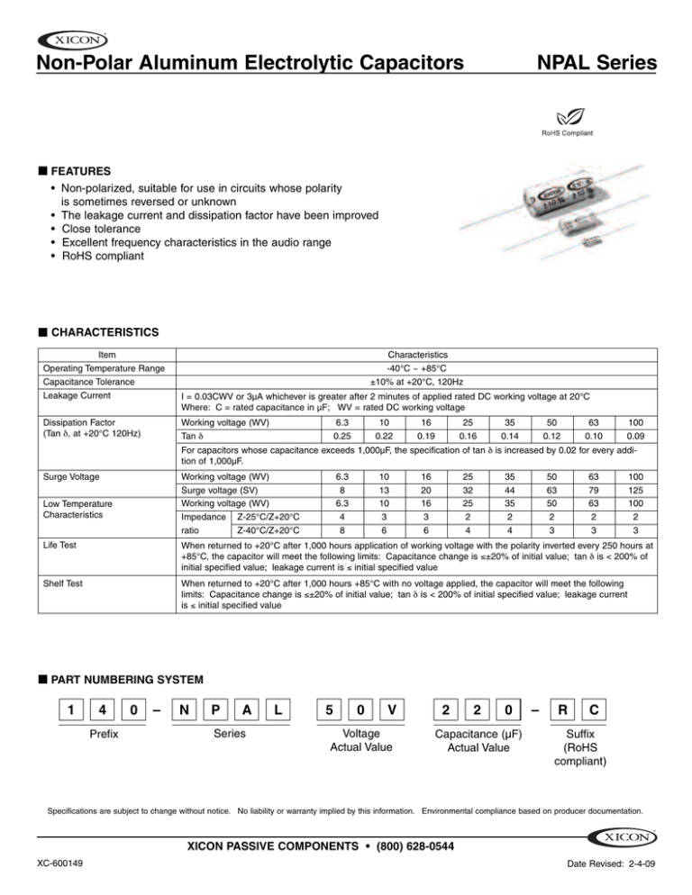
Non-Polar Aluminum Electrolytic Capacitors NPAL Series FEATURES • Non-polarized, suitable for use in circuits whose polarity is sometimes reversed or unknown • The leakage current and dissipation factor have been improved • Close tolerance • Excellent frequency characteristics in the audio range • RoHS compliant CHARACTERISTICS Item Operating Temperature Range Capacitance Tolerance Leakage Current Characteristics -40°C ~ +85°C ±10% at +20°C, 120Hz I = 0.03CWV or 3µA whichever is greater after 2 minutes of applied rated DC working voltage at 20°C Where: C = rated capacitance in µF; WV = rated DC working voltage Dissipation Factor (Tan δ, at +20°C 120Hz) Working voltage (WV) Tan δ 6.3 0.25 10 0.22 16 0.19 25 0.16 35 0.14 50 0.12 63 0.10 100 0.09 Surge Voltage Working voltage (WV) Surge voltage (SV) Working voltage (WV) Impedance Z-25°C/Z+20°C ratio Z-40°C/Z+20°C 6.3 8 6.3 4 8 10 13 10 3 6 16 20 16 3 6 25 32 25 2 4 35 44 35 2 4 50 63 50 2 3 63 79 63 2 3 100 125 100 2 3 For capacitors whose capacitance exceeds 1,000µF, the specification of tan δ is increased by 0.02 for every addition of 1,000µF. Low Temperature Characteristics Life Test When returned to +20°C after 1,000 hours application of working voltage with the polarity inverted every 250 hours at +85°C, the capacitor will meet the following limits: Capacitance change is ≤±20% of initial value; tan δ is < 200% of initial specified value; leakage current is ≤ initial specified value Shelf Test When returned to +20°C after 1,000 hours +85°C with no voltage applied, the capacitor will meet the following limits: Capacitance change is ≤±20% of initial value; tan δ is < 200% of initial specified value; leakage current is ≤ initial specified value PART NUMBERING SYSTEM 1 4 Prefix 0 – N P A Series L 5 0 V Voltage Actual Value 2 2 0 Capacitance (µF) Actual Value – R C Suffix (RoHS compliant) Specifications are subject to change without notice. No liability or warranty implied by this information. Environmental compliance based on producer documentation. XICON PASSIVE COMPONENTS • (800) 628-0544 XC-600149 Date Revised: 2-4-09 Non-Polar Aluminum Electrolytic Capacitors NPAL Series DIMENSIONS AND PERMISSIBLE RIPPLE CURRENT Vent ≥ 10 ø ød 20 min. Value (µF) 6.3 x 16 8 x 16 8 x 16 10 x 17 13 x 22 13 x 27 øD ±β max. 20 min. 10 0.6 2.0 1.0 13 0.6 2.0 1.0 Working Voltage (WV); Dimensions: øD x L (mm); Ripple Current: mA/RMS @ 120Hz, 85°C 10 16 25 35 50 63 6.3 øD x L 0.1 0.22 0.33 0.47 1 2.2 3.3 4.7 10 15 22 33 47 100 220 330 470 1000 2200 L ±α max. Lead Dimensions (mm) øD 6.3 8 ød 0.6 0.6 α 1.5 1.5 β 0.5 0.5 mA 118 195 239 333 508 836 øD x L mA 6.3 x 13 6.3 x 12 8 x 13 8 x 16 10 x 17 10 x 21 13 x 22 16 x 28 71 85 147 254 312 389 603 1000 øD x L 6.3 x 13 6.3 x 13 8 X 13 8 x 16 10 x 17 10 x 21 13 x 22 13 X 27 16 X 36 mA 61 80 95 155 268 344 436 664 1121 øD x L 6.3 x 12 8 x 13 8 x 13 10 x 17 10 x 21 13 x 22 13 x 27 16 x 28 18 x 42 mA 69 85 113 192 298 387 483 781 1355 øD x L mA 6.3 X 13 46 6.3 x 13 8 x 16 8 X 16 10 x 17 13 x 22 13 X 27 16 x 28 16 x 37 74 101 120 205 338 433 552 857 øD x L 6.3 x 12 6.3 x 12 6.3 x 12 6.3 x 12 6.3 x 12 6.3 x 12 6.3 x 12 6.3 x 12 6.3 x 12 8 x 13 8 x 16 8 x 16 10 x 17 10 x 21 10 x 27 16 x 28 16 x 33 18 x 42 mA 5 7 9 10 16 23 29 34 54 71 89 109 152 232 381 500 668 1054 øD x L 6.3 x 13 6.3 x 13 6.3 x 13 6.3 x 13 6.3 x 13 6.3 x 13 6.3 x 12 6.3 x 13 8 x 13 8 x 16 8 x 16 10 x 17 10 x 21 13 x 22 16 x 27 16 x 33 18 x 42 16 0.8 2.0 1.0 18 0.8 2.0 1.0 100 mA 5 8 10 12 18 27 31 40 59 97 97 139 174 269 447 567 792 øD x L 6.3 x 12 6.3 x 12 6.3 x 12 6.3 x 12 6.3 x 12 6.3 x 12 6.3 x 16 6.3 x 16 8 x 16 10 x 26 10 x 22 10 x 24 10 x 30 16 x 28 16 x 37 mA 5 8 10 12 18 27 35 42 69 120 153 203 317 501 Specifications are subject to change without notice. No liability or warranty implied by this information. Environmental compliance based on producer documentation. XICON PASSIVE COMPONENTS • (800) 628-0544 XC-600149 Date Revised: 2-4-09
