Unit 5 Electrical Damped Oscillation
advertisement

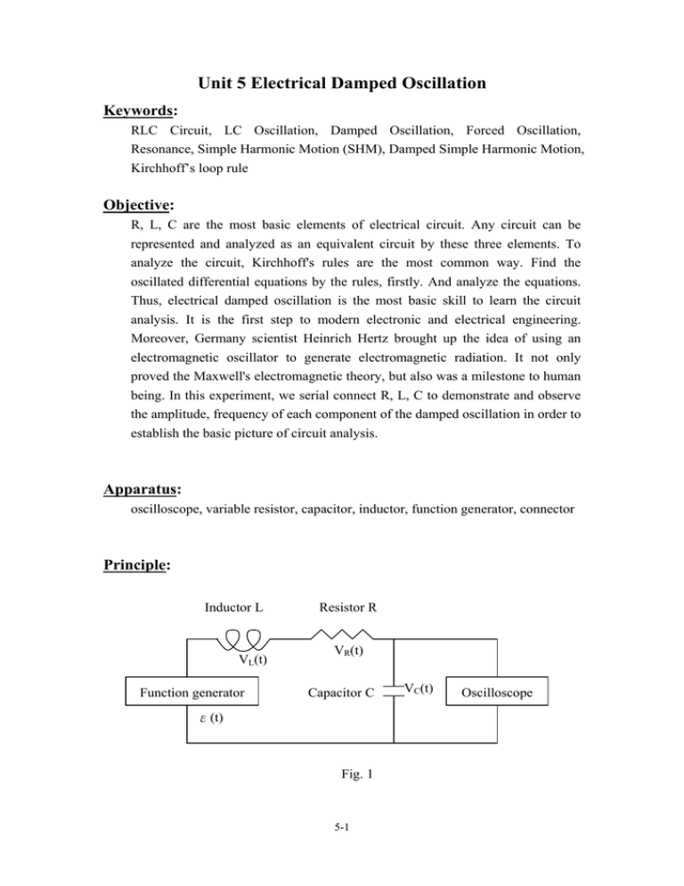
Unit 5 Electrical Damped Oscillation Keywords: RLC Circuit, LC Oscillation, Damped Oscillation, Forced Oscillation, Resonance, Simple Harmonic Motion (SHM), Damped Simple Harmonic Motion, Kirchhoff’s loop rule Objective: R, L, C are the most basic elements of electrical circuit. Any circuit can be represented and analyzed as an equivalent circuit by these three elements. To analyze the circuit, Kirchhoff's rules are the most common way. Find the oscillated differential equations by the rules, firstly. And analyze the equations. Thus, electrical damped oscillation is the most basic skill to learn the circuit analysis. It is the first step to modern electronic and electrical engineering. Moreover, Germany scientist Heinrich Hertz brought up the idea of using an electromagnetic oscillator to generate electromagnetic radiation. It not only proved the Maxwell's electromagnetic theory, but also was a milestone to human being. In this experiment, we serial connect R, L, C to demonstrate and observe the amplitude, frequency of each component of the damped oscillation in order to establish the basic picture of circuit analysis. Apparatus: oscilloscope, variable resistor, capacitor, inductor, function generator, connector Principle: Inductor L VL(t) Function generator Resistor R VR(t) Capacitor C ε(t) Fig. 1 5-1 VC(t) Oscilloscope Figure 1 shows a resistor, an inductor, and a capacitor in series connected. The function generator is treated as the electromotive force (emf) of the circuit. Observe the voltage of the capacitor through oscilloscope to illustrate the variation of the signal. Firstly, let us analyze theoretically as the basic of observation. From Kirchhoff's rules: The algebraic sum of the changes in potential around a closed loop is zero. Therefore, V R (t ) + VL (t ) + VC (t ) = ε (t ) (1) Where ε(t) is the emf given by function generator. VR(t)、VL(t)、VC(t) are the potential changes of R, L, C. If we represented the characteristic of resistor, capacitor, and inductor by the potential change VC(t), we can get: ○ 1 Capacitor characteristic: Q (t ) = VC (t ) ⋅ C => i (t ) = ○ 2 Ohm's law: V R (t ) = i (t ) ⋅ R = dV (t ) dQ (t ) =C C dt dt dVC (t ) ⋅ RC dt ○ 3 Inductor characteristic: V L (t ) = L ⋅ d 2VC (t ) di (t ) = LC ⋅ dt dt 2 substitute into (1), we can get the second order differential equation of the circuit. d 2VC (t ) R dVC (t ) 1 ε (t ) + ⋅ + ⋅ VC (t ) = 2 L dt LC LC dt (2) Through solving this differential equation VC(t), we can get the expected function. However, from (2), the solution of the equation depends on ε(t). Consider two conditions as shown in fig. 2. ε(t) is a square wave or a sine wave. ε(t) ε(t) ε0 OA B O t (A) t (B) Fig. 2 5-2 (I) ε(t) is a square wave. Assume the frequency is low. We can treat the circuit under two conditions. (point A and B in fig.2-(A) ) At point A, emf changes from -ε0 to ε0. Capacitor is being charged by emf until it is full of electricity; at point B, emf changes from ε0 to -ε0. Capacitor is discharging until the electrical energy is depleted in the circuit. Therefore, we descript it in two parts: (a) Charging process: ε(t) = ε0, the 2nd order differential equation can be represented as: d 2VC (t ) R dVC (t ) ε 1 + ⋅ + ⋅ VC (t ) = 0 2 L dt LC LC dt (3) Consider the initial condition of the charging process: VC (t = 0) = −ε 0 . The solution of the 2nd order differential equation is: Amplitude term Oscillating term Vc(t) = ε0(1− 2e−β t cosω t) where β = R ,ω = 2L (4) 1 R β − ( ) 2 , φ = tan −1 ,j = − 1 LC 2L ω (b) Discharging process: ε(t) = - ε0, the 2nd order differential equation can be represented as: d 2VC (t ) R dVC (t ) 1 VC (t ) = −ε 0 L dt LC dt Consider the initial condition of the charging process: VC (t = 0) = ε 0 . The 2 + + solution of the 2nd order differential equation is: Vc (t ) = 2 0 e − βt cos( ⋅ t ) − ε ω ε0 (5) Do the plot of (4) and (5) versus time, we can get the expected function of charging and discharging process of damped circuit. Oscillation Initial square wave 5-3 We can see that the amplitude terms of both (4) and (5) have the common factor e − β t . And the oscillating terms have the common factor cos(ωt). The functions are exactly the same as the damped oscillation of spring in mechanics. The amounts of β and ω depend on the amount of R, L, and C. And it determines the oscillating behavior as shown below: 2 1 ⎛ R⎞ (1) For ⎜ ⎟ > , ω is an imaginary number and cos(ωt) = cosh(jωt) , ⎝ 2L⎠ LC which is a hyperbolic cosine function. There is no oscillation. It's called "over damped". 2 1 ⎛ R⎞ (2) For ⎜ ⎟ = , ω = 0 and cos(ωt) = 1. There is no oscillation, either. ⎝ 2L⎠ LC It's called "critical damped". 2 1 ⎛ R⎞ (3) For ⎜ ⎟ < , ω is a real number. Oscillation occurs. It's called ⎝ 2 L⎠ LC 2 1 ⎛ R ⎞ "under damped". If ⎜ ⎟ ⟨⟨ , the frequency of the oscillation would ⎝ 2 L ⎠ LC approach ω0 = 1 , called nature angular frequency. LC Take discharging process as an example, these different conditions can be shown on fig. 3. Fig. 3 5-4 (II) ε(t) is sine wave. Let the emf as ε (t ) = ε 0 cos(ω d t ) . We can get: d 2VC (t ) R dVC (t ) 1 ε + + VC (t ) = 0 cos(ω d t ) 2 L dt LC LC dt (6) This equation is the same as forced oscillations in mechanics. Neglecting the temporary-state oscillation, solution of the steady-state oscillation is: Amplitude term Vc (t ) = Oscillating term ( − ε0 ω d C) R 2 + (ωL − 1 ωd C )2 ⋅ sin(ω d t − φ ) (7) Similarly, from (7), the voltage is oscillating with the angular frequency ω d . The amplitude depends on the frequency. As shown in figure 4, which is the plot 1 of amplitude term A( ω d ) to angular frequency ω d . When ω d = ω = , LC natural angular frequency, the amplitude reaches the maximum amount. It is 1 is called resonance angular frequency. called resonance. ω = LC Therefore, different kinds of electrical filters can be made for different applications through varying the amount of R, L, and C. A(ωd) R min R mid R max ω0 Fig. 4 5-5 ωd Instructions: ( I ) Charging and discharging process of square wave: 1. Firstly, take one resistor, one capacitor, and one inductor. Be sure that the function generator and the oscilloscope are off. Serious connect R, L, C as shown in fig. 1. Use channel one of oscilloscope to observe the signal. 2. Calculate the nature frequency. Turn the function generator on. Select 1 of the nature frequency. square wave. Set the frequency to about 20 Turn the oscilloscope on. Adjust the time scale so that you can see 2~3 periods of oscillation. Adjust the voltage scale so that you can observe the signal easily and clearly. Q1: Observe the signal of CH1, can you observe the under damped oscillation? If not, how do you adjust the amount of resistor (or capacitor, or inductor) so that you can observe the oscillation? 3. Adjust the amount of R, L, C to observe an under damped oscillation. Adjust the time scale of the oscilloscope, read the period of the 2π 。 oscillation, and calculate ϖ = T Q2: Compare your calculation to equation (4). Are they the same? 4. Take one (dis)charging process, measure the damping of the amplitude and do the plot versus time. Use curve fitting to find β. Q3: Compare your plot to equation (5). Does it fit the theory e − β ⋅t ? 5. Vary the amount of capacitor for totally 5 times and repeat the procedure to find each ω. Do the plot of ω2 to the amounts of capacitor. Q4: Does your plot fit the theory? 6. Keep the amount of inductor and capacitor as constant. Vary the amount of the resistor; can you observe the critical damped and over damped oscillation? Q5 : Can you observe “critical damped” and “over damped” oscillation? What’s the difference between them? ( II ) Forced oscillation of sine wave: 1. The circuit is set as step (I). Observe the signals of emf and the voltage of the capacitor at the same time. 2. Calculate the natural angular frequency ω0. 3. Set the output of the function generator to sine wave, the amplitude to about 1V, (Be sure that the OFFSET switch is off.), and the frequency 5-6 to about natural frequency. Switch the channel of the oscilloscope to CH1 to measure the frequency and amplitude of capacitor voltage. Q6: Compare the frequency you measure to the frequency of the function generator, are they the same? 4. Adjust the frequency of the function generator to find the maximum amplitude of capacitor voltage. Put the frequency, amplitude, and the phase down. Compare your data to the theory. If the maximum amplitude exceeds the scope of the oscilloscope, lower the amplitude of the function generator appropriately. 5. As the frequency of the function generator increases, you would find that the amplitude would decrease. Increase the frequency so that the amplitudes are 0.2, 0.4, 0.6, and 0.8 of the maximum amplitude. Put the frequencies and the amplitudes down. 6. Adjust the frequency of the function generator back to find the maximum amplitude of capacitor voltage. As the frequency of the function generator decreases, you would find that the amplitude would decrease. Lower the frequency so that the amplitudes are 0.2, 0.4, 0.6, and 0.8 of the maximum amplitude. Put the frequencies and the amplitudes down. 7. Vary the resistor twice, repeat the step 4, 5, 6. Do the plot of signal amplitudes to frequencies ωd. Compare to figure 4; does it fit to the theory? Q7: Do you observe the phenomena shown in figure 4? (i.e. the curve is flatter when the amount of the resistor becomes larger) Remark: 1. Be sure that the circuit is not short connected before you turn the power on. Question: Q8: Please find some applications of electrical damped oscillation in daily life. 5-7 Force Oscillation: R L A.C C Vc (t) V (t) Assume the alternating current power source is V (t ) = V ⋅ Cos (ω ⋅ t ) , the current of the circuit is i (t ) . The circuit would satisfy the 2nd order differential equation: d 1 V (t ) = V ⋅ Cos(ω ⋅ t ) = i (t ) R + L i (t ) + ∫ i (t )dt dt C where R, L, C are the amounts of the resistor, the inductor, and the capacitor We use phasor technique to solve the damped oscillation circuit: Assume the impedance of the circuit is Z. 1 Then Z = R + jωL + (where j ≡ − 1 ) jωC According to the ohm's law, we can get the effective current I of the circuit: Ve jwt Ve jwt Ve jwt I= = = 1 1 Z R + jω L + R + j (ωL − ) jω C ωC 1 ωL − Ve jwt ωC = , whereφ = tan −1 R 1 2 jφ R 2 + (ωL − ) ⋅e ωC V = ⋅ e j ( wt −φ ) 1 2 R 2 + (ωL − ) ωC Get the current of the circuit i(t) by taking the real part of I i (t ) = Re[ I ] = V 1 2 R 2 + (ωL − ) ωC ⋅ cos(ω ⋅ t − φ ) Thus, the output voltage Vc(t) is Vc(t ) = 1 i (t )dt = = C∫ V 1 2 ωC R + (ωL − ) ωC 2 5-8 ⋅ sin(ω ⋅ t − φ )


