Partially liquid-filled hollow-core photonic crystal
advertisement

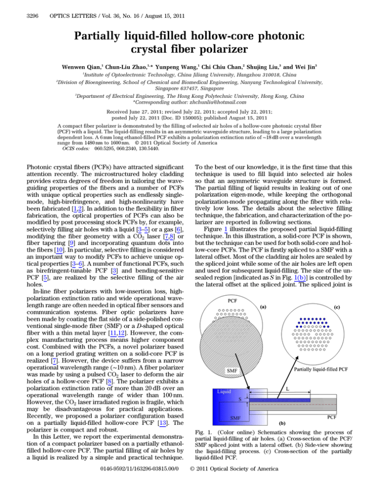
3296 OPTICS LETTERS / Vol. 36, No. 16 / August 15, 2011 Partially liquid-filled hollow-core photonic crystal fiber polarizer Wenwen Qian,1 Chun-Liu Zhao,1,* Yunpeng Wang,1 Chi Chiu Chan,2 Shujing Liu,3 and Wei Jin3 1 2 Institute of Optoelectronic Technology, China Jiliang University, Hangzhou 310018, China Division of Bioengineering, School of Chemical and Biomedical Engineering, Nanyang Technological University, Singapore 637457, Singapore 3 Department of Electrical Engineering, The Hong Kong Polytechnic University, Hong Kong, China *Corresponding author: zhchunliu@hotmail.com Received June 27, 2011; revised July 22, 2011; accepted July 22, 2011; posted July 22, 2011 (Doc. ID 150005); published August 15, 2011 A compact fiber polarizer is demonstrated by the filling of selected air holes of a hollow-core photonic crystal fiber (PCF) with a liquid. The liquid-filling results in an asymmetric waveguide structure, leading to a large polarization dependent loss. A 6 mm long ethanol-filled PCF exhibits a polarization extinction ratio of ∼18 dB over a wavelength range from 1480 nm to 1600 nm. © 2011 Optical Society of America OCIS codes: 060.5295, 060.2340, 130.5440. Photonic crystal fibers (PCFs) have attracted significant attention recently. The microstructured holey cladding provides extra degrees of freedom in tailoring the waveguiding properties of the fibers and a number of PCFs with unique optical properties such as endlessly singlemode, high-birefringence, and high-nonlinearity have been fabricated [1,2]. In addition to the flexibility in fiber fabrication, the optical properties of PCFs can also be modified by post processing stock PCFs by, for example, selectively filling air holes with a liquid [3–5] or a gas [6], modifying the fiber geometry with a CO2 laser [7,8] or fiber tapering [9] and incorporating quantum dots into the fibers [10]. In particular, selective filling is considered an important way to modify PCFs to achieve unique optical properties [3–6]. A number of functional PCFs, such as birefringent-tunable PCF [3] and bending-sensitive PCF [5], are realized by the selective filling of the air holes. In-line fiber polarizers with low-insertion loss, highpolarization extinction ratio and wide operational wavelength range are often needed in optical fiber sensors and communication systems. Fiber optic polarizers have been made by coating the flat side of a side-polished conventional single-mode fiber (SMF) or a D-shaped optical fiber with a thin metal layer [11,12]. However, the complex manufacturing process means higher component cost. Combined with the PCFs, a novel polarizer based on a long period grating written on a solid-core PCF is realized [7]. However, the device suffers from a narrow operational wavelength range (∼10 nm). A fiber polarizer was made by using a pulsed CO2 laser to deform the air holes of a hollow-core PCF [8]. The polarizer exhibits a polarization extinction ratio of more than 20 dB over an operational wavelength range of wider than 100 nm. However, the CO2 laser irradiated region is fragile, which may be disadvantageous for practical applications. Recently, we proposed a polarizer configuration based on a partially liquid-filled hollow-core PCF [13]. The polarizer is compact and robust. In this Letter, we report the experimental demonstration of a compact polarizer based on a partially ethanolfilled hollow-core PCF. The partial filling of air holes by a liquid is realized by a simple and practical technique. 0146-9592/11/163296-03$15.00/0 To the best of our knowledge, it is the first time that this technique is used to fill liquid into selected air holes so that an asymmetric waveguide structure is formed. The partial filling of liquid results in leaking out of one polarization eigen-mode, while keeping the orthogonal polarization-mode propagating along the fiber with relatively low loss. The details about the selective filling technique, the fabrication, and characterization of the polarizer are reported in following sections. Figure 1 illustrates the proposed partial liquid-filling technique. In this illustration, a solid-core PCF is shown, but the technique can be used for both solid-core and hollow-core PCFs. The PCF is firstly spliced to a SMF with a lateral offset. Most of the cladding air holes are sealed by the spliced joint while some of the air holes are left open and used for subsequent liquid-filling. The size of the unsealed region [indicated as S in Fig. 1(b)] is controlled by the lateral offset at the spliced joint. The spliced joint is Fig. 1. (Color online) Schematics showing the process of partial liquid-filling of air holes. (a) Cross-section of the PCF/ SMF spliced joint with a lateral offset. (b) Side-view showing the liquid-filling process. (c) Cross-section of the partially liquid-filled PCF. © 2011 Optical Society of America August 15, 2011 / Vol. 36, No. 16 / OPTICS LETTERS then immersed into a liquid and the unsealed holes are filled with the liquid by capillarity action. The filling length (L) is controlled by filling time [4]. Compared to the previous selective filling techniques, this technique is more easily operated and has a lower cost. In [4], selective filling was mainly based on the different filling speeds that depend on the sizes of air holes and the technique was limited to filling PCFs with different air hole sizes. In [5,6], selective filling was achieved by use of a femtosecond IR laser to selectively open some of the air holes, which involves complex laser processing and a higher experimental cost. In our experiment, the hollow-core PCF used is the Crystal Fiber’s HC-1550-02 photonic bandgap fiber and the diameters of the fiber cladding and the microstructured holey region are 125 μm and 80 μm, respectively. The PCF was cleaved by use of a Fujikura CT-30 cleaver and spliced to a SMF by a Fujikura FSM-50S fusion splicer. Figure 2(a) shows a schematic of the fusion splicing process. The lateral offset was controlled by adjusting the SMF position in the X-field view by manually operating the fusion splicer. To avoid or minimize the collapse of the air holes in the filling region, the gapset position was fixed to the right side of the PCF/SMF joint, as shown in Fig. 2(a). In this position, the PCF was far away from the electrodes and it was affected only weakly by the arc discharge during the splicing process. At the same time, a lower discharge current and a shorter discharge duration were used, and discharge parameters were adjusted repeatedly to obtain a better performance splice. A good mismatched fusion splicing can be realized to keep air holes of the PCF’s partial filling region open, by properly selecting gapset position, discharge current and duration, combined with a suitable gap and overlap between the PCF and the SMF. Figures 2(b) and 2(c) show fusion splicer images of a good quality splicing in the X-field and Y -field views. For this splicing, the SMF position was offset approximately 40 μm from the PCF in the veritical direction [see Fig. 2(b)]. The gapset position was 30 μm on the right side from the center of the electrodes, with a 10 μm gap. Ethanol (ACS grade) was chosen as the filling liquid. A 16 mm long PCF can be partially filled with ethanol within 30 seconds. Figures 3(a) and 3(b) show the cross sectional images of the unfilled and the partially Fig. 2. (Color online) (a) Schematic diagram of the splicing process. (b) X-field and (c) Y -field views of a PCF/SMF spliced joint. 3297 Fig. 3. (Color online) Optical microscopic images of cross section of (a) the unfilled PCF and (b) the partially filled PCF. ethanol-filled PCF sections. The filled and unfilled regions are clearly distinguished in Fig. 3(b) and ethanolfilled most of the unsealed air holes. Certain air holes, which are located near the boundary of the filled and the unfilled regions, were not filled. This might be because these holes were collapsed near the spliced joint during the fusion splicing process. A full-vector finite element method was used to analyze mode fields of the two eigen polarization states of the partially ethanol-filled PCF. The model used is shown in Fig. 4(a), which closely resembles the partially filled PCF as shown in Fig. 3(b). The pitch or spacing between air holes is Λ ¼ 3:9 μm, and the air hole diameter to pitch ratio is d=Λ ≈ 97%. The red region indicates the liquid-filled region and the index of the liquid is taken as 1.36048 at room temperature (25 °C). Figures 4(b) and 4(c) show the mode fields of X-polarization and Y -polarization modes at 1550 nm. Obviously the X-polarization mode is well confined to the core, while the Y -polarization mode has a significant leakage into the cladding region. The partially liquid-filled PCF has a large polarization dependence loss due to the asymmetric refractive index distribution in the cladding. A detailed analysis of polarization dependent loss of partially liquid-filled PCF has been reported previously [13]. With a fiber cleaver, a 6 mm long PCF was then cut from a longer length of partially ethanol-filled PCF and then fusion spliced at both ends to standard SMF pigtails with a conventional splicing condition (core to core). The total loss of the two spliced joints is about 8 dB. A broadband light source with a polarizer was used as a linearly polarized source to test the performance of the fiber polarizer. The measured loss spectra for various angles of input polarization from 0° to 90° are shown in Fig. 5. The maximum and minimum losses are approximately 27:5 dB and 9:5 dB at 90° and 0°, respectively. The polarization extinction ratio, which is the difference between the maximum and the minimum losses, is estimated to be Fig. 4. (Color online) (a) Model structure used in simulation. Red region is the ethanol-filled region. Mode field distribution of (b) X-polarization and (c) Y -polarization mode. 3298 OPTICS LETTERS / Vol. 36, No. 16 / August 15, 2011 Fig. 5. (Color online) Loss spectra for various linearly polarized lights with different input polarization angles. Fig. 6. (Color online) Polarization extinction ratios of the partial ethanol-filled polarizer at different temperatures. approximately 18 dB in the wavelength range of 1480 nm to 1600 nm. The loss around 1470 nm has large variations, corresponding to the band edge of the hollow-core PCF transmission window. The insertion loss of the partially ethanol-filled section is about 1:5 dB, which is equal to the difference between the minimum loss (∼9:5 dB) and the splicing loss (∼8 dB). We also tested the temperature dependent extinction ratio of the partially liquid-filled polarizer, and the results are shown in Fig. 6. The polarization extinction ratio has only weak dependence on temperature and the variation is less than 2 dB for three different temperatures of 10 °C, 25 °C, and 40 °C. A better performance on the polarization extinction ratio can be optimized by adjusting the length of the partially liquid-filled PCF and the size of the liquid-filled region on PCF cladding. A longer length of the partial liquid-filled PCF and a larger liquid-filled region on the PCF can lead to a larger polarization extinction ratio of the partially liquid-filled polarizer [13]. Liquid with a lower sensitivity to temperature would be a better choice to improve the temperature stability of the device. On the other hand, when a liquid with a larger thermal-optic coefficient is used as the filling material, a temperaturetunable device may be realized. By using a curable polymer as filling material, all solid fiber polarizing devices may be made. In conclusion, a simple technique for the partial filling of liquid into cladding air holes of a PCF was demonstrated, in which only a conventional fusion splicer and capillary action were needed. With the technique, a compact fiber polarizer was fabricated. A fiber polarizer made of a 6 mm long partially ethanol-filled PCF exhibits a polarization extinction ratio of ∼18 dB and an insertion loss ∼1:5 dB over a wide operational wavelength range from 1480 nm to 1600 nm. By optimizing the filling length and the size of the liquid-filled region, such polarizers with better performances can be obtained. The proposed partial filling technique is simple and flexible to filling liquid into different air holes of PCFs and could be applied to fabricate other functional photonic devices and sensors. This work was supported by the National Basic Research Program of China (973 Program) under Grant No. 2010CB327804, the major project of theEducation Department in Zhejiang province of China under Grant No. Z200909231 and the Qianjiang Talents Program of Zhejiang Province of China under Grant No. QJD0902005. References 1. P. Russell, Science 299, 358 (2003). 2. J. C. Knight, Nature 424, 847 (2003). 3. C. Kerbage, P. Steinvurzel, P. Reyes, P. S. Westbrook, R. S. Windeler, A. Hale, and B. J. Eggleton, Opt. Lett. 27, 842 (2002). 4. Y. Huang, Y. Xu, and A. Yariv, Appl. Phys. Lett. 85, 5182 (2004). 5. Y. Wang, X. Tan, W. Jin, S. Liu, D. Ying, and Y. L. Hoo, Opt. Express 18, 12197 (2010). 6. J. Ju, H. F. Xuan, W. Jin, S. Liu, and H. L. Ho, Opt. Lett. 35, 3886 (2010). 7. Y. Wang, L. Xiao, D. Wang, and W. Jin, Opt. Lett. 32, 1035 (2007). 8. H. F. Xuan, W. Jin, J. Ju, Y. P. Wang, M. Zhang, Y. B. Liao, and M. H. Chen, Opt. Lett. 33, 845 (2008). 9. W. Wadsworth, A. Witkowska, S. Leon-Saval, and T. Birks, Opt. Express 13, 6541 (2005). 10. Z. Wu, Z. Mi, P. Bhattacharya, T. Zhu, and J. Xu, Appl. Phys. Lett. 90, 171105 (2007). 11. R. A. Bergh, H. C. Lefevre, and H. J. Shaw, Opt. Lett. 5, 479 (1980). 12. R. B. Dyott, J. Bello, and V. A. Handerek, Opt. Lett. 12, 287 (1987). 13. W. Qian, C.-L. Zhao, J. Kang, X. Dong, Z. Zhang, and S. Jin, Opt. Commun. 284, 4800 (2011).


