1. General Description of Aluminum Electrolytic Capacitors
advertisement
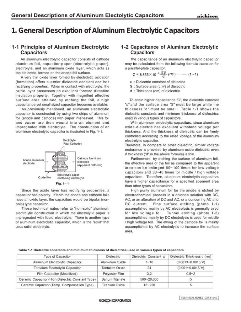
General Descriptions of Aluminum Electolytic Capacitors 1. General Description of Aluminum Electrolytic Capacitors 1-1 Principles of Aluminum Electrolytic Capacitors 1-2 Capacitance of Aluminum Electrolytic Capacitors An aluminum electrolytic capacitor consists of cathode aluminum foil, capacitor paper (electrolytic paper), electrolyte, and an aluminum oxide layer, which acts as the dielectric, formed on the anode foil surface. A very thin oxide layer formed by electrolytic oxidation (formation) offers superior dielectric constant and has rectifying properties. When in contact with electrolyte, the oxide layer possesses an excellent forward direction insulation property. Together with magnified effective surface area attained by etching the foil, a high capacitance yet small sized capacitor becomes available. As previously mentioned, an aluminum electrolytic capacitor is constructed by using two strips of aluminum foil (anode and cathode) with paper interleaved. This foil and paper are then wound into an element and impregnated with electrolyte. The construction of an aluminum electrolytic capacitor is illustrated in Fig. 1-1. The capacitance of an aluminum electrolytic capacitor may be calculated from the following formula same as for a parallel-plate capacitor. -- 8 εS (1 - 1) (µF) C = 8.855 10 d , ,,,,,,, ,,,,,, , ,,,,,,, Electrolyte (Real Cathode) Anode aluminum electrode Oxide film Cathode Aluminum electrode (Apparent Cathode) Electrolytic paper containing electrolyte Fig. 1 - 1 Since the oxide layer has rectifying properties, a capacitor has polarity. If both the anode and cathode foils have an oxide layer, the capacitors would be bipolar (nonpola) type capacitor. These technical notes refer to "non-solid" aluminum electrolytic construction in which the electrolytic paper is impregnated with liquid electrolyte. There is another type of aluminum electrolytic capacitor, which is the "solid" that uses solid electrolyte. ε : Dielectric constant of dielectric S : Surface area (cm2) of dielectric d : Thickness (cm) of dielectric To attain higher capacitance "C", the dielectric constant " ε " and the surface area "S" must be large while the thickness "d" must be small. Table 1-1 shows the dielectric constants and minimum thickness of dielectrics used in various types of capacitors. With aluminum electrolytic capacitors, since aluminum oxide dielectric has excellent withstand voltage per thickness. And the thickness of dielectric can be freely controlled according to the rated voltage of the aluminum electrolytic capacitor. Therefore, in compare to other dielectric, similar voltage endurance is provided by aluminum oxide dielectric even if thickness ("d" in the above formula) is thin. Furthermore, by etching the surface of aluminum foil, the effective area of the foil as compared to the apparent area can be enlarged 80~100 times for low voltage capacitors and 30~40 times for middle / high voltage capacitors. Therefore, aluminum electrolytic capacitors have a higher capacitance for a specified apparent area than other types of capacitors. High purity aluminum foil for the anode is etched by electrochemical process in a chloride solution with DC, AC, or an alteration of DC and AC, or a concurring AC and DC current. Fine surface etching (photo 1-1) accomplished mainly by AC electrolysis is generally used for low voltage foil. Tunnel etching (photo 1-2) accomplished mainly by DC electrolysis is used for middle / high voltage foil. The ething of the cathode foil is mainly accomplished by AC electrolysis to increase the surface area. Table 1-1 Dielectric constants and minimum thickness of dielectrics used in various types of capacitors Type of Capacitor Dielectric Aluminum Electrolytic Capacitor Aluminum Oxide Tantalum Electrolytic Capacitor Film Capacitor (Metallized) Dielectric Constant ε Dielectric Thickness d (µm) 7~10 (0.0013~0.0015/ V) Tantalum Oxide 24 (0.001~0.0015/ V) Polyester Film 3.2 0.5~2 Ceramic Capacitor (High Dielectric Constant Type) Barium Titanate 500~20,000 5 Ceramic Capacitor (Temp. Compensation Type) Titanium Oxide 15~250 5 TECHNICAL NOTES CAT.8101C NICHICON CORPORATION General Descriptions of Aluminum Electolytic Capacitors Section Surface Photo 1-1 Surface and section photo of etched aluminum foil for low voltage capacitors. Section (Replica) Surface Photo 1-2 Surface and section photo of etched aluminum foil for middle / high voltage capacitors. TECHNICAL NOTES CAT.8101C NICHICON CORPORATION General Descriptions of Aluminum Electolytic Capacitors 1-3 Dielectric (Aluminum Oxide Layer) 0.0013~0.0015 (µm/ V). Expanded photography of a dielectric (aluminum oxide layer) on the foil that has not been etched (plain foil) is shown in photo 1-3. The fabrication reaction of the dielectric can be expressed as follows: [Al(OH2)6]3+ 1) Al3++6H2O 3+ Al(OH)3+3H2O+3H+ 2) [Al(OH2)6] Al2O3+3H2O 3) 2Al(OH)3 20V Fomed Photo 1-3 dielectric dielectric dielectric A high purity etched aluminum foil is anodized in a boric acid-ammonium water type solution, for exsample, to form an aluminum oxide layer on its surface. This aluminum oxide layer is what we call the dielectric of the aluminum electrolytic capacitor. The DC voltage that is applied to the foil to oxidize the anode foil is called "Forming Voltage". The thickness of the dielectric is nearly proportional to the forming voltage and measures approximately 100V Fomed 250V Fomed Enlarged photo of oxide layer formed on a non-etched plain aluminum foil. Photo 1-4 Enlarged photo of middle, high voltage formed foil. (Condition of oxide layer formation in a pit) 1-4 Electrolyte Anode foil and a cathode foil facing each other are interleaved with electrolytic paper and wound into a cylindrical shape. This is called a "capacitor element." At this stage, it has configuration of a capacitor when considers electrolytic paper and the aluminum oxide layer to be dielectric, however, the unit has few capacitance. When this capacitor element is impregnated with liquid electrolyte, the anode foil and cathode foil are electrically connected. With the aluminum oxide layer formed on the anode foil acting as the sole dielectric, a capacitor with a high value of capacitance is now attainable. That is to say that the electrolyte is now functioning as a cathode. The basic characteristics required of an electrolyte are listed below: (1) It must be electrically conductive (2) It must have a forming property to heal any flaws on the dielectric oxide of the anode foil. (3) It must be chemically stable with the anode and cathode foils, sealing materials, etc. (4) It must have superior impregnation characteristics (5) Its vapor pressure must be low. The above characteristics of electrolyte greatly influence the various characteristics of aluminum electrolytic capacitors. For this reason, the proper electrolyte is determined by the electrical ratings, operating temperatures and the application of the capacitor. NICHICON CORPORATION TECHNICAL NOTES CAT.8101C General Descriptions of Aluminum Electolytic Capacitors 1-5 Manufacturing Process of Aluminum Electrolytic Capacitors Process Etching (Enlargement of the Surface Area) Main Materials Contents High purity aluminum foil A 0.05~0.11 mm thick anode foil and a 0.02~0.05 mm thick cathode foil are continuously etched electrochemically in a chloride solution with an AC or DC current. This enlarges the effective surface area of the aluminum foils to attain smaller capacitor sizes. Chloride Pure water Forming Etched foil (Formation of the Dielectric) Borate, etc. Slitting The process develops aluminum oxide (Al203) to form a capacitor dielectric. A high purity etched aluminum foil is anodized in a boric acidammonium water type solution, for exsample, to form an aluminum oxide film on the surface of the cathode foil. As for the anode foil, an low DC voltage is sometimes used for formation, but there are also situations where formation is not conducted. Pure water A foli is slit into specified widths according to capacitor case sizes. Anode foil Cathode foil Slited foils (anode/cathode) Winding Electrolytic paper Leade Anode and cathode foils interleaved with an electrolytic paper are wound into a cylindrical capacitor element, with leads being connected to both foils. Winding aftixing material Lead Winding aftixing material Element Foil Electrolytic paper Fig. 1 - 2 TECHNICAL NOTES CAT.8101C NICHICON CORPORATION General Descriptions of Aluminum Electolytic Capacitors Prosess Main Materials Element Impregnation Electrolyte Contents Elements are impregnated with liquid electrolyte. The clearance between the two electrode foils is filled with liquid electrolyte. With this impregnation, an element can function as a capacitor. The impregnated element, case and end seal are assmbled. Elements Electrolyte For the end seal , a rubber packing, a rubber lined bakelite (with terminals) or a molded plastic plate (with terminals) are Case (usually aluminum) used. End seal After assembly, the capacitors are covered with exterior Rubber packing, housing material. Sleeving is not used for laminate case Rubber-bakelite with terminals products, such as surface mount capacitors. Impregnated elements Assembly & Finishing ( Mold plastic with terminals Exterior housing material (Sleeving, bottom plate, etc.) ) Aluminum rivet Lead wire Terminal Rubber-bakelite Aluminum lead tab Curled section ,,,,,, ,,,, ,,, Aluminum lead tab Rubber packing ,,, , ,,,, ,,,, , ,, , Curled section Aluminum case Sleeving Aluminum case Element Sleeving Element ,,,,,,,,,,,,,,,,,,,,, ,,,,,,,,,,,,,,,,,,,,, ,,,,,,,,,,,,,,,,,,,,, ,,,,,,,,,,,,,,,,,,,,, ,,,,,,,,,,,,,,,,,,,,, ,,,,,,,,,,,,,,,,,,,,, ,,,,,,,,,,,,,,,,,,,,, ,,,,,,,,,,,,,,,,,,,,, Fig. 1 - 3 Fig. 1 - 4 Element fixing material (may or may not be - used) Bottom plate Nylon laminate casing for laminate products (sleeveless) Aging Processing Assembled products DC voltage is applied under high temperature conditions to reform the oxide film. Plastic platform Leads are processed and the plastic platform is attached to surface mount capacitors. Depending on customer specification, the lead cutting, forming, snap - in and taping are processed. Accessories, such as mounting braket, are attached. Taping material ,,,, ,,,, ,,,, ,,, Accessories (Capacitor mounting braket terminal screws , etc.) Fig. 1 - 5 An inspection based on the standard specification and test requirements is performed to guarantee the quality of products. Inspection Packaging Packaging materials Shipping TECHNICAL NOTES CAT.8101C NICHICON CORPORATION General Descriptions of Aluminum Electolytic Capacitors 1-6 Characteristics 1-6-1 Capacitance The capacitance of the dielectric portion of the anode aluminum foil can be calculated with the following formula (discussed in 1-1) : Z = R2+(ω L -- ω C ) ε S (µF) -- 8 Ca = 8.855 10 1 d The cathode foil has a capacitance (Cc) that uses the oxide film, which formed by the forming voltage or formed naturally during storage (generally it should be 1V or less), as a dielectric. According to the construction of aluminum electrolytic capacitors, Ca and Cc are connected in a series. Therefore, the capacitance can be determined by the following formula: Ca C c Ca + Cc 10 The standard capacitance tolerance is 20%(M); however, capacitors with a capacitance tolerance of 10%(K), etc. are also manufactured for special usage. The capacitance of aluminum electrolytic capacitors changes with temperature and frequency of measurement, so the standard has been set to a frequency of 120Hz and o temperature of 20 C. 10-1 R 10-2 10-3 XL Xc 102 103 104 105 106 Frequency (Hz) Fig. 1 - 8 C Capacitance (F) r R r Equivalent parallel resistance of anode oxide film (Ω) R Equivalent series resistance (Ω) L C Fig. 1 - 6 L Equivalent series inductance ( H ) A reactance value due to the equivalent series inductance "L" is extremely small at low frequencies (50Hz~1kHz) and can be regarded as zero. Therefore, the following formula can be set up. tanδ = Z R =ωCR Xc DF = tan δ δ (1/ωc) 1 Z 1-6-2 Equivalent Series Resistance (R), Dissipation Facter (tanδ), Impedance (Z) The equivalent circuit of an aluminum electrolytic capacitor is shown below, The equivalent series resistance is also known as "ESR". Xc 2 Its relation with frequencies is shown by a model curve. The inductance "L" is mainly from the wound electrode foils and the leads. ESR "R" is from resistance of the electrode foils, the electrolyte, the leads and each connection. R (Ω), Z(Ω) C= The impedance can be expressed by : 1 Z= + jw L + R jω C Its absolute value can be expressed by : PF = cos θ θ R Q = 1 tan δ (ω = 2 π f) Fig. 1 - 7 (1 - 2) (1 - 3) 100 (%) R = = Z Xc = R R 2 R + 2 (1 - 4) ( ω1C ) (1 - 5) 1-6-3 Leakage Current The causes of leakage current in aluminum electrolytic capacitors are listed below : 1)Distorted polarization of dielectric (aluminum oxide layer) 2)Resolution and formation of dielectric 3)Moisture absorption by dielectric 4)Breakdown of dielectric due to the existence of chlorine or iron particles. The leakage current value can be decreased by proper selection of materials and production methods; however, cannot be totally eliminated. Leakage current is also dependent upon time, applied voltage and temperature. The specified leakage current value is measured after the rated voltage of the capacitor is applied at room temperature for a specified time period. When selecting a capacitor for a particular application, characteristics such as temperature dependency, aging stability and etc. must be taken into account. TECHNICAL NOTES CAT.8101C NICHICON CORPORATION General Descriptions of Aluminum Electolytic Capacitors 1-6-4 Temperature Characteristics Aluminum electrolytic capacitors have liquid electrolyte. This electrolyte has properties (conductivity, viscosity, etc.) that have rather conspicuous temperature characteristics. Electrical conductivity increases as the temperature increases and reduces as the temperature decreases. Therefore, the electrical characteristics of aluminum electrolytics are affected by temperature more than other types of capacitors. The following section explains the relationship between temperature and capacitance, tangent delta, ESR, impedance and leakage current. 10 -25oC 1 tan δ 0.01 100 +20oC tan δ +65oC +105oC 0.1 50V 1000µF 105o C 0.01 100 10k 1k Frequency (Hz) Fig. 1 - 10 Tanδ vs. Frequency Characteristics at 120HZ -10 -20 10 -30 50V 1000µF 105oC -40 20 10 -40 -20 0 20 40 60 Temperature (o C) 80 100 120 ESR( Ω ) Impedance( Ω ) -60 Capacitance change (%) -25oC 1 200V 470µF 105 o C 0 -10 1 at 120HZ 0.01 100 -30 10 -40 -40 ESR +20oC -20 -60 Impedance -25oC 0.1 -20 0 20 40 60 Temperature (o C) 80 100 120 Fig. 1 - 9 Capacitance vs. Temperature Characteristics 1k 10k Frequency (Hz) +65oC +105oC 100k 200V 470µF 105oC -25oC ESR( Ω ) Impedance( Ω ) Capacitance change (%) 0 10k 1k Frequency (Hz) 10 200V 470µF 105oC 2) Tanδ, Equivalent Series Resistance (ESR), Impedance The Tanδ, equivalent series resistance (ESR) and impedance changes with temperature and frequency. An example of the general characteristics is shown in Fig. 110 and 1-11. 10 +20oC +65oC +105oC 0.1 1) Capacitance The capacitance of aluminum electrolytic capacitors increases as the temperature increases and decreases as the temperature decreases. The relationship between temperature and capacitance is shown in Fig. 1-9. 20 50V 1000µF 105oC 1 Impedance ESR 0.1 +20oC +65oC 0.01 100 +105oC 1k 10k Frequency (Hz) 100k Fig. 1 - 11 Impedance, ESR vs. Frequency Characteristics TECHNICAL NOTES CAT.8101C NICHICON CORPORATION General Descriptions of Aluminum Electolytic Capacitors 4) Leakage Current The leakage current increases as the temperature increases and decreases as the temperature decreases. Fig. 1-12 shows the relationship between temperature and leakage current. 1000 Leakage current (µA) 3) Impedance Ratio o The ratio between the impedance at 20 C and the impedance at various temperatures is called the impedance ratio. Impedance ratio becomes smaller as smaller change of ESR and capacitance with temperature. The quality of performance at low temperatures is particularly expressed with the impedance ratio at 120Hz. 50V 1000 µF 105oC Measured after 1 minute application of rated voltage 100 10 1 -20 Leakage current (µA) 1000 0 20 40 60 Temperature (oC) 80 100 120 80 100 120 200V 470 µF 105oC Measured after 5 minutes application of rated voltage 100 10 1 -20 0 20 40 60 Temperature (oC) Fig. 1 - 12 Leakage current vs. Temperature Characteristic TECHNICAL NOTES CAT.8101C NICHICON CORPORATION
