IB PHYSICS HL MULTIPLE CHOICE REVIEW
advertisement

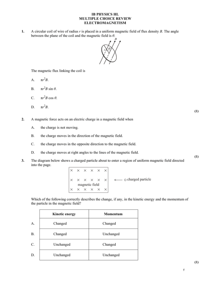
IB PHYSICS HL MULTIPLE CHOICE REVIEW ELECTROMAGNETISM 1. A circular coil of wire of radius r is placed in a uniform magnetic field of flux density B. The angle between the plane of the coil and the magnetic field is θ. B r The magnetic flux linking the coil is A. πr2B. B. πr2B sin θ. C. πr2B cos θ. D. πr2B. (1) 2. A magnetic force acts on an electric charge in a magnetic field when A. the charge is not moving. B. the charge moves in the direction of the magnetic field. C. the charge moves in the opposite direction to the magnetic field. D. the charge moves at right angles to the lines of the magnetic field. (1) 3. The diagram below shows a charged particle about to enter a region of uniform magnetic field directed into the page. charged particle magnetic field Which of the following correctly describes the change, if any, in the kinetic energy and the momentum of the particle in the magnetic field? Kinetic energy Momentum A. Changed Changed B. Changed Unchanged C. Unchanged Changed D. Unchanged Unchanged (1) 1 4. A magnetic force acts on an electric charge in a magnetic field when A. the charge is not moving. B. the charge moves in the direction of the magnetic field. C. the charge moves in the opposite direction to the magnetic field. D. the charge moves at right angles to the lines of the magnetic field. (1) 5. The currents in two parallel wires are I and 3I in the directions shown in the diagram below. wire 1 wire 2 I 3I The magnetic force on wire 2 due to the current in wire 1 is F. The magnitude of the force on wire 1 due to the current in wire 2 is A. F . 3 F . 2 B. C. F. D. 3F. (1) 6. Two long, parallel, straight wires X and Y carry equal currents into the plane of the page as shown. The diagram shows arrows representing the magnetic field strength B at the position of each wire and the magnetic force F on each wire. B Y (field strength at X due to Y) X F F Y B X (field strength at Y due to X) The current in wire Y is doubled. Which diagram best represents the magnetic field strengths and forces? A. BY F X 2F Y BX B. BY X 2F 2F Y BX C. 2B Y X 2F F Y 2B X D. 2B Y X 2F 2F Y BX (1) 2 7. An electron is moving in air at right angles to a uniform magnetic field. The diagram below shows the path of the electron. The electron is slowing down. region of magnetic field Which one of the following correctly gives the direction of motion of the electron and the direction of the magnetic field? Direction of motion Direction of magnetic field A. clockwise into plane of paper B. clockwise out of plane of paper C. anti-clockwise into plane of paper D. anti-clockwise out of plane of paper (1) 8. The diagram below shows the variation with time of the magnetic flux linkage through a coil. flux linkage 0 t1 t2 t3 t4 0 time At which times is the induced emf equal to zero? A. t1 and t3 B. t2 and t4 C. t1 and t2 D. t1 and t4 (1) 3 9. A lamp of resistance R is connected in series to a source of alternating voltage. The rms value of the voltage is 20 V. The variation with time t of the power P dissipated in the light bulb is shown below. 100 80 60 P/W 40 20 0 0 t The best estimate for the value of the resistance of the filament of the lamp is A. 4.0 . 4.0 2 Ω. B. 8.0 . C. D. 8.0 2 Ω. (1) 10. A metal ring is placed in a region of uniform magnetic field such that the plane of the ring is perpendicular to the direction of the field. The field strength is increasing at a constant rate. ring magnetic field The sketch-graph shows the variation with time t of the magnetic flux linking the ring. 0 t 0 Which of the following graphs best shows the variation with time t of the induced current I in the ring? A. I B. 0 0 C. t D. I 0 0 I t 0 0 t 0 0 t I (1) 4 11. The Earth’s magnetic field may be compared with that of a bar magnet. Which of the following diagrams correctly shows the orientation of the bar magnet in this model? A. B. geographical north pole geographical north pole N S N C. S D. geographical north pole geographical north pole S N N S (1) 12. A transformer has a primary coil with Np turns and a secondary coil with Ns turns. An alternating voltage supply of frequency f and r.m.s. value Vp is connected to the primary coil. Which of the following correctly gives the frequency and r.m.s. voltage in the secondary coil? Frequency A. Ns f Np B. f C. D. Np Ns f Voltage Np Ns Np Ns f Vp Vp Ns Vp Np Ns Vp Np (1) 5 13. The diagram shows a coil of wire wound on an iron core. A When the switch is closed, the ammeter reading gradually increases from zero to a maximum value. What is the explanation for this gradual growth of current? A. An e.m.f. is induced in the coil. B. The e.m.f. of the battery is increasing. C. The iron core has a very low resistance. D. The battery has a large internal resistance. (1) 14. High voltages are used for the transmission of electric power over long distances because A. high voltages can be stepped down to any required value. B. larger currents can be used. C. power losses during transmission are minimized. D. transformers have a high efficiency. (1) 15. Drops of a liquid are being sprayed vertically upwards into the air by a hose in a region where the Earth’s magnetic field is directed horizontally as shown in the diagram below. motion of drop direction of magnetic field hose As each drop leaves the hose it becomes negatively charged. Which of the following describes the direction of the magnetic force acting on the drops? A. Downwards B. Upwards C. Out of the paper D. Into the paper (1) 6 16. The variation with time of the current in the primary coil of an ideal transformer is shown below. current 0 B C A D time At which time will the magnitude of the induced e.m.f. in the secondary coil be maximum? A. A B. B C. C D. D (1) MARK SCHEME! 1. B [1] 2. D [1] 3. C [1] 4. D [1] 5. C [1] 6. D [1] 7. D [1] 8. A [1] 9. C [1] 10. C [1] 11. A [1] 12. D [1] 13. A [1] 14. C [1] 15. C 16. C [1] [1] 7


