EQUIPOTENTIAL BONDING IN AN ELECTRICAL INSTALLATION
advertisement

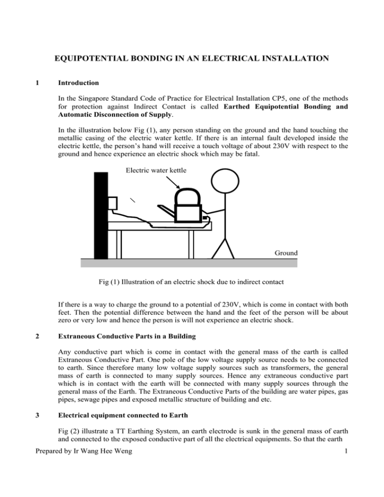
EQUIPOTENTIAL BONDING IN AN ELECTRICAL INSTALLATION 1 Introduction In the Singapore Standard Code of Practice for Electrical Installation CP5, one of the methods for protection against Indirect Contact is called Earthed Equipotential Bonding and Automatic Disconnection of Supply. In the illustration below Fig (1), any person standing on the ground and the hand touching the metallic casing of the electric water kettle. If there is an internal fault developed inside the electric kettle, the person’s hand will receive a touch voltage of about 230V with respect to the ground and hence experience an electric shock which may be fatal. Electric water kettle Ground Fig (1) Illustration of an electric shock due to indirect contact If there is a way to charge the ground to a potential of 230V, which is come in contact with both feet. Then the potential difference between the hand and the feet of the person will be about zero or very low and hence the person is will not experience an electric shock. 2 Extraneous Conductive Parts in a Building Any conductive part which is come in contact with the general mass of the earth is called Extraneous Conductive Part. One pole of the low voltage supply source needs to be connected to earth. Since therefore many low voltage supply sources such as transformers, the general mass of earth is connected to many supply sources. Hence any extraneous conductive part which is in contact with the earth will be connected with many supply sources through the general mass of the Earth. The Extraneous Conductive Parts of the building are water pipes, gas pipes, sewage pipes and exposed metallic structure of building and etc. 3 Electrical equipment connected to Earth Fig (2) illustrate a TT Earthing System, an earth electrode is sunk in the general mass of earth and connected to the exposed conductive part of all the electrical equipments. So that the earth Prepared by Ir Wang Hee Weng 1 Extraneous conductive part. e.g. water pipe IEF = I1 + IB Electrical equipment exposed conductive part a b c R J IB N K d d B Supply source earth electrode Y (I1 + IB) Installation’s e Earth Electrode. RE = 2.1 I1 Insulator Protective conductor General Mass of Earth I1 g f IB Fig. (2) Potential difference received by a person in an electrical installation fault current, IEF, can be flow back to the supply source via the earth electrode and the general mass of the earth. The earth fault current flows through a closed loop abcdefgNa, and the impedance formed by the impedance of the circuit conductors and earth electrode resistance around this closed loop is called Earth Fault Loop Impedance, ZS. Assuming the earth electrode resistance, RE= 2.1 Ohm and the earth fault loop impedance, ZS= 2.3 Ohm. For a supply phase voltage Vph= 230V, the potential difference received by the both hands of the person will be calculated as follow: Hand to hand touch voltage, VJK = ( Vph / ZS ) x RE = 230/2.3 x 2.1 = 210 Volt 4 Main Equipotential Bonding in Electrical Installation Fig. (3) is similar to Fig. (2), except that a Main Earth Terminal and a Main Equipotential Bonding Conductor is added to the electrical installation of Fig. (2). Assumed, ZS = (Resistance of the path gab of the supply source) + RCPC + R1 + RE = 2.3 (Resistance of the path gab) = ZS - RCPC - R1 - RE = 2.3 - 0.08 – 0.001 – 2.1= 0.119 The resistance of (R1 + RE) are in parallel with (R2 + RP), their effective resistance is RT. 1/RT = 1/(R1 + RE) + 1/(R2 + RP) = 1/(0.001 + 2.1) + 1/(0.002 + 0.01) RT = 0.0119 The earth fault loop impedance for Fig. (3) is ZS = (Resistance of the path “gab” of the supply source) + RCPC + RT = 0.119 + 0.08 + 0.01 = 0.2109 The earth fault current, IEF = VPH / ZS = (230/0.2109) = 1090A Prepared by Ir Wang Hee Weng 2 Extraneous conductive part. e.g. water pipe Fixed Electrical equipment 20A Type-B MCB IEF =I1+I2+IC a L b R VPH K J N N IEF IC Y Insulator Main Earthing Terminal Supply source earth electrode Installation’s Earth Electrode. RE = 2.1 IEF g IEF Circuit Protective Conductor. RCPC = 0.08 B General Mass of Earth IC I2 B I1 Main equipotential Bonding Conductor. R2 = 0.002 Earthing Conductor. R1 = 0.001 C C C Water pipe buried in ground. RP = 0.01 Fig. (4) Electrical installation with TT-Earthing System The human body impedance of hand to hand is assumed to be about 1000 Ohm and hence its shunting effect to the electrical installation is negligibly small. The current IC flow through the human body is very small compare with IEF, however it can leads to fatal electric shock. The potential difference across the two hand, VJK = VCPC + VBC = 87.2 + 2.16 = 89.36 V Hence, the person shall experience an electric shock based on 89.36V with the presence of the main equipotential bonding conductor for the same installation. This is 57.45% lower than the potential difference of 210V as describe in paragraph 3. The parameters which can be varied are RCPC , R1 , R2 , RE and RP in general. Let the earth resistance of the water pipe increases to RP = 1 . From calculation, the value of RT= 0.6784, ZS= 0.8774, IEF= 262A, VET= 177.74V, I2= 177.39A, VBC= 0.35V, VCPC= 20.96V and touch voltage VJK= 21.35V. In conclusion, in terms of magnitude of touch voltage, unearthed equipment is the highest, earthed only equipment can be high, but earthed equipotential bonding can give the smallest magnitude of touch voltage. Prepared by Ir Wang Hee Weng 3


