Three Reservoir Problem - EFM
advertisement

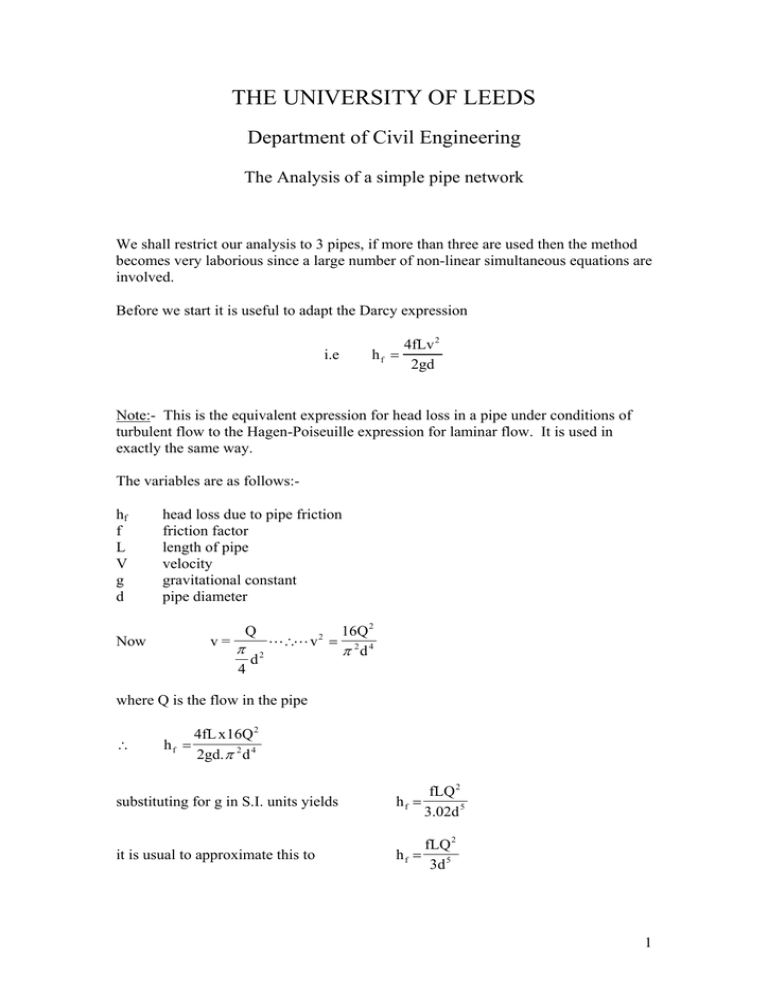
THE UNIVERSITY OF LEEDS Department of Civil Engineering The Analysis of a simple pipe network We shall restrict our analysis to 3 pipes, if more than three are used then the method becomes very laborious since a large number of non-linear simultaneous equations are involved. Before we start it is useful to adapt the Darcy expression 4fLv 2 hf = 2gd i.e Note:- This is the equivalent expression for head loss in a pipe under conditions of turbulent flow to the Hagen-Poiseuille expression for laminar flow. It is used in exactly the same way. The variables are as follows:hf f L V g d head loss due to pipe friction friction factor length of pipe velocity gravitational constant pipe diameter v= Now Q π 4 d2 L∴L v 2 = 16Q 2 π 2d 4 where Q is the flow in the pipe ∴ hf = 4fL x16Q 2 2gd. π 2 d 4 fLQ 2 3.02d 5 substituting for g in S.I. units yields hf = it is usual to approximate this to fLQ 2 hf = 3d 5 1 Now consider a 3 pipe system 4 When three or more pipes meet at a junction then the following basic principles must apply:(i) The continuity equation must be obeyed i.e. the total flow into the junction must equal the total flow out of the junction (Kirchoff’s law). (ii) at any one point these can only be one value of head. (iii) Darcy’s equation must be satisfied for each pipe. It is usual to ignore minor losses, it is impracticable to take them into account, fortunately they are usually negligible. There is still one problem to be resolved and that is that whatever formula is used for friction loss it does not take any account of the direction of flow. The total head always falls in the direction of flow but Darcy’s equation will give a positive hf regardless of the sign of the velocity. The direction of flow is usually obvious but whenever it is in doubt a direction has to be assumed - if it is incorrect then no physically possible solution can be obtained. In our diagram the flow in pipe b has been assumed to be from the junction J to B. The heads at A, B and C are known. The head at J is unknown so are the flows in all the pipes. The direction of flow in pipes a and c is obvious. For steady conditions the following relationships can be written down z a − h j = h fa (1) h j − zb = h fb (2) h j − zc = h fc (3) Qa = Qb + Qc (4) hf = f(Q) therefore these four equations can be used to solve for the four unknowns hj, Qa, Qb and Qc. 2 fLQ 2 Now h f = 3d 5 f may or may not be equal for all three pipes, even if it is equal an algebraic solution is tedious, it is easier to use a method of trial and error as follows:(i) estimate a value of the head at the junction, hj (ii) substitute this into equations 1, 2 and 3 hence a first estimate of hf and Q can be determined for each pipe (iii) check these values of Q in equation 4 (iv) if the flow into J is too great then a larger trial value of hj is required and vice versa (v) return to step (ii). Note:- If the direction of flow in pipe b was wrongly assumed then no solution will be found. If this is so then the four equations become z a − h j = h fa zb − h j = h fb h j − zc = h fc Qa + Qb = Qc Inspection of these equations shows that both sets are identical when hj = zb, this suggests that a good point to start the iteratation is hj = zb the direction of flow will then become apparent after the first step. img\analysis.doc 3
