system pressure control
advertisement

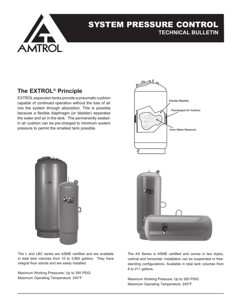
SYSTEM PRESSURE CONTROL TECHNICAL BULLETIN The EXTROL® Principle EXTROL expansion tanks provide a pneumatic cushion capable of continued operation without the loss of air into the system through absorption. This is possible because a flexible diaphragm (or bladder) separates the water and air in the tank. The permanently sealedin air cushion can be pre-charged to minimum system pressure to permit the smallest tank possible. The L and LBC series are ASME certified and are available in total tank volumes from 10 to 3,963 gallons. They have integral floor stands and are easily installed. Maximum Working Pressures: Up to 300 PSIG Maximum Operating Temperature: 240°F Flexible Bladder Precharged Air Cushion Inner Water Reservoir The AX Series is ASME certified and comes in two styles, vertical and horizontal. Installation can be suspended or freestanding configurations. Available in total tank volumes from 8 to 211 gallons. Maximum Working Pressure: Up to 300 PSIG Maximum Operating Temperature: 240°F Temperature and Pressure Effects in Hydronic Heating and Cooling Systems A system is designed to operate within a certain temperature band. One limit is set by the ambient temperature and the other is determined by the function of the system. For example, the temperature is reduced in a chilled water system and increased in a heating system. Minimum System Temp. Maximum System Temp. Heating Ambient Average Design Temp. Chilled Water Average Design Temp. Ambient System Type The volume of water within a system varies with the temperature. At any point above 39.2°F, an increase in temperature results in an increase in volume (see Figure 1). Therefore, as the temperature of a system changes within the operating band, a change in volume must be accommodated. Pressure Pressure in the system will fluctuate during the operating cycle. It is the function of the expansion tank to prevent an increase in pressure to a level where safety relief valves may operate. Knowledge of the pressure range occurring at the expansion tank is essential in sizing an EXTROL. Minimum Pressure at EXTROL Minimum Operating Pressure = Static Pressure + ® Pressure to Prevent Boiling i) S tatic pressure – is the pressure exerted by a column of water. To calculate, estimate height of system in feet above the EXTROL and multiply by 0.433 to give PSIG. ii) Pressure to prevent boiling – water boils at 212°F in normal atmospheric pressure, but as the pressure increases, the boiling point also rises. Therefore, if a system is to operate over 212°F without boiling, the pressure must be increased over the static level. The increase necessary for various temperatures is shown in Table 1. Figure 1 - Net Expansion of Water 1.06 1.05 SPECIFIC VOLUME Temperature Affects Volume 1.04 1.03 1.02 1.01 1.00 39.2 60 80 100 120 140 160 TEMPERATURE 180 200 220 240 Table 1 - Pressure to Prevent Boiling Maximum Operating Temperature in °F Approximate Positive Pressure Required 200° 2 PSIG 205° 3 PSIG 210° 5 PSIG 215° 7 PSIG 220° 9 PSIG 225° 11 PSIG 230° 13 PSIG 235° 16 PSIG 240° 19 PSIG Figure 2 - Analyzing the Critical Points In System Maximum Pressure at EXTROL® The upper pressure limit at which the tank will operate is the sum of the minimum pressure plus the system allowable pressure increase. Maximum Operating Pressure = Minimum Operating Pressure + Allowable Pressure Increase for System 5 PSIG - Adequate Positive Pressure 50' = 22 PSIG Static Pressure Pressure Change for Expansion = 30 PSI 100' = 43 PSIG Static Pressure Relief Setting … 80 PSIG Pump Effect ... 15 PSIG After evaluating the pressure change for expansion at all critical points in the system, the smallest one is chosen as the allowable pressure increase for the system. (See Figure 2). Example – evaluating pressure change for expansion at the boiler: Pump Head 20 PSI Relief Setting … 100 PSIG Pump Effect ... 20 PSIG Relief valve setting at boiler........................................... 100 PSIG Minus 10 percent weepage protection............................ -10 PSIG Pressure Change for Expansion at Boiler = 22 PSIG Equals maximum allowable pressure at boiler................. 90 PSIG Minus minimum pressure at boiler.................................. -48 PSIG Maximum Allowable Pressure Increase at Tank Can Be No More Than 22 PSI Equals permissible pressure change at boiler................. 42 PSIG Minus change due to pump operation............................. -20 PSIG Equals pressure change for expansion at boiler.............. 22 PSIG Pump Effect If the EXTROL tank is downstream and the pump is upstream of the component, the pressure will increase when the pump operates. If the reverse is true, pressure will decrease when the pump is running. This is because the hydro-pneumatic tank is the only component that is unaffected by pump operation. The only time pressure at the tank varies is when system temperature changes and expanded water flows to or from the EXTROL, thus changing the volume of the captive air cushion. The point at which the EXTROL is connected is an important consideration. By locating it at pump suction, it is assured that all pump pressure effects are positive and vacuums cannot be drawn. EXTROL connection at any other point is feasible and occasionally may be desirable, but the pump pressure effects should be considered. Figure 3 - System and Pump Characteristics 30 PRESSURE - FT H2O The pressure developed by the system pump is determined by the pipe network to which it is connected. Every system has a unique operating characteristic band, often simplified to a curve on a graph (See Figure 3). The point where system and pump characteristics intercept defines the point of pump operation. The pressure developed by the system pump is dissipated in overcoming friction as fluid flows through the system. The amount of this pressure change at any given component varies, depending on its proximity to the point of tank connection. PUMP CURVE 25 SYSTEM OPERATING ENVELOPE 20 15 DESIGN OPERATING POINT 10 SYSTEM CURVE 5 0 0 10 20 30 40 50 SPECIFIC FLOW - G.P.M. 60 Typical Specification Pressurization and Air Elimination System Typical Air Elimination System Top Floor Riser To Upper Floors The tank shall be supported by steel legs or a base (integral ring mount) for a vertical installation. Each tank will have a heavy duty replaceable butyl bladder. P P Deaeration Valve and Pressure Gauge Air Seperator & Eliminator Air Seperator & Eliminator Location When Location When Pressure Drop Pressure Drop Thru Lateral is Low Thru Lateral is High Pressure Gauge P Pump Pressure Gauge P Additional Pumps Pressure Gauge P Automatic Fill Valve Temperature Gauge T Air Seperator & Eliminator (Recommended) Water Meter Drain Valve Boiler The manufacturer shall be AMTROL Inc. The manufacturer will have at least five years experience in the fabrication of bladder-type ASME expansion tanks. 3. Air Separator (Tangential Type): All free air originally contained in the system, and all entrained air bubbles carried by system water shall be eliminated at all system points as indicated in the drawings. The air separator shall be cast iron or welded steel, constructed, tested and stamped in accordance with Section VIII, Division 1 of the ASME Code for a working pressure of (150) (___) PSIG as manufactured by AMTROL Inc. The pressure drop through the air separator at the specified flow rate shall be as shown on the drawings. Comprising Connection of EXTROL to System 1. AX Series Expansion Tank (Diaphragm type pre-pressurized): Unlike a conventional tank, the permanently sealed air cushion does not The pressurization system shall include an EXTROL® diaphragm-type expansion tank which will accommodate the expanded water of the system generated within the normal operating temperature range, limiting this pressure increase at those components in the system to the maximum allowable pressure at those components. It shall maintain minimum operating pressure necessary to eliminate all air. The only air in the system shall be the permanent sealed-in air cushion contained in the diaphragm-type tank, Model No. ____. Dimensions shall be as indicated on the drawings. The expansion tank shall be welded steel, constructed, tested and stamped in accordance with Section VIII, Division 1 of the ASME Code for a working pressure of (125) (___)PSIG and air pre-charged. The tank shall be supported by steel legs or a base (integral ring mount) for a vertical installation or steel saddles for a horizontal installation. Each tank will have a heavy duty butyl diaphragm. The manufacturer shall be AMTROL Inc. The manufacturer will have at least five years experience in the fabrication of diaphragm-type ASME expansion tanks. 2. L & LBC Series Expansion Tank (replaceable bladder-type prepressuriezed): The pressurization system shall include an EXTROL replaceable bladder-type expansion tank which will accommodate the expanded water of the system generated within the normal operating temperature range, limiting this pressure increase at those components in the system to the maximum allowable pressure at those components. It shall maintain minimum operating pressure necessary to eliminate all air. The only air in the system shall be the permanent sealed-in air cushion contained in the replaceable bladdertype tank, Model No. ____. Dimensions shall be as indicated on the drawings. The expansion tank shall be welded steel construction, tested and stamped in accordance with Section VIII, Division 1 of the ASME Code for a working pressure of (125) (175) (250) (___)PSIG and air pre-charged. require replenishment so DO NOT connect it to a separator or other “air control” device. As with any expansion tank, it is recommended that the EXTROL is connected to the suction side of the pump. This will prevent the pump head from becoming subtractive which may result in entry of air and vapor formation at high points in the system. By connecting the tank on the boiler return, displacement of the coolest system water into the tank is ensured, thus reducing energy wastage. Low pressure drop components, such as separators and boilers, may be located between the point of connection and pump suction if desired. The design of the system will dictate the feasibility of this. Natural convection losses and the entry of air into the tank are eliminated by connecting to the side or underside of the main pipe. Any potential air traps in the piping connecting the tank to the system should be vented. Typical Connection Diagram To Air Separator & Pump Suction Pressure Gauge I To Boiler Strainer Lock Shield Gate Valve Pressure Reducing Valve EXTROL Diaphram/ Bladder Type Prepressurized Expansion Tank 1400 Division Road, West Warwick, RI USA 02893 T: 800.426.8765 F: 800.293.1519 www.amtrol.com © 2014 AMTROL Inc. Reduced Pressure Zone Type Back Flow Preventer Meter Mark of the Originator MC# 1140 Part #: 9017-100 (01/14)


