Halogen, Incandescent, and Magnetic Low-Voltage Dimmer
advertisement
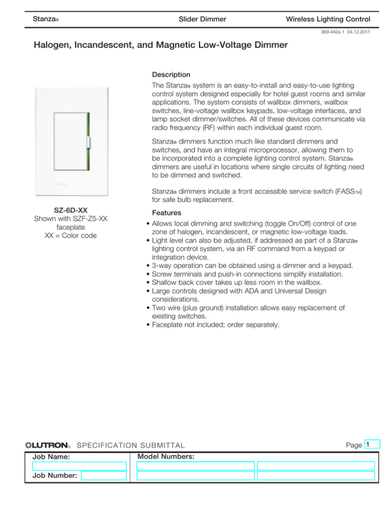
Stanza® Slider Dimmer Wireless Lighting Control 369-442a 1 04.12.2011 Halogen, Incandescent, and Magnetic Low-Voltage Dimmer Description The Stanza® system is an easy-to-install and easy-to-use lighting control system designed especially for hotel guest rooms and similar applications. The system consists of wallbox dimmers, wallbox switches, line-voltage wallbox keypads, low-voltage interfaces, and lamp socket dimmer/switches. All of these devices communicate via radio frequency (RF) within each individual guest room. Stanza® dimmers function much like standard dimmers and switches, and have an integral microprocessor, allowing them to be incorporated into a complete lighting control system. Stanza® dimmers are useful in locations where single circuits of lighting need to be dimmed and switched. Stanza® dimmers include a front accessible service switch (FASSTM) for safe bulb replacement. SZ-6D-XX Shown with SZF-Z5-XX faceplate XX = Color code R Features •Allows local dimming and switching (toggle On/Off) control of one zone of halogen, incandescent, or magnetic low-voltage loads. •Light level can also be adjusted, if addressed as part of a Stanza® lighting control system, via an RF command from a keypad or integration device. •3-way operation can be obtained using a dimmer and a keypad. •Screw terminals and push-in connections simplify installation. •Shallow back cover takes up less room in the wallbox. •Large controls designed with ADA and Universal Design considerations. •Two wire (plus ground) installation allows easy replacement of existing switches. •Faceplate not included; order separately. S pecificat ion Sub mit t al Job Name: Job Number: Model Numbers: Page 1 Stanza® Slider Dimmer Wireless Lighting Control 369-442a 2 04.12.2011 Specifications System Communication and Capacity: Regulatory Approvals: •UL •NOM •cUL and ICA •FCC (Complies with the limits for a Class B digital device, pursuant to Part 15 of the FCC rules) Load: •40 W minimum, 600 W maximum halogen, incandescent, or 450 W / 600 VA magnetic low-voltage •Derated if ganged; see derating chart •Do not install dimmer to control standard receptacles or motor-operated appliances. Contact Lutron for dimmable receptacle solution. Power: •Operating voltage: 120 V 50/60 Hz Key Design Features: •Backlight of slider glows green; section of slider track turns amber for programming indication •Adjustable maximum light level provides energy savings and extended bulb life •Power failure memory: if power is interrupted, when the power is restored, lights will return to their previously set level prior to the interruption •On a single tap, lights alternately fade to preset level or turn off •Light level can be fine-tuned by moving the slider up or down until the desired light level is reached •Requires Stanza®-specific faceplate (order separately) •Requires a 1-gang U.S. wallbox: 3.5 in (89 mm) deep recommended; 2.25 in (57 mm) deep minimum •Can be ganged with other Stanza® controls or with decorator controls using multigang Stanza® faceplates R S pecificat ion Sub mit t al Job Name: Job Number: Model Numbers: •Dimmers communicate with other Stanza® system components through radio frequency (RF) at 434 MHz •Multiple RF channels and thousands of system addresses prevent interference between systems •Each dimmer counts as 1 toward the basic system maximum of 31 RF devices (maximum devices can be increased to 100 if an SZ-CI-PRG is present in the system) Environment: •Ambient operating temperature: 32 - 104 °F (0 - 40 °C) •Maximum 90% non-condensing relative humidity •Indoor use only Warranty: •1-year limited warranty standard. 2-year parts and labor warranty, with 8-year pro-rated parts replacement on systems that include factory startup. For more information: www.lutron.com/TechnicalDocumentLibrary/ Warranty_CommercialSystems.pdf Color Codes: (Satin Colors®) Button ColorCode BiscuitBI EggshellES MerlotMR MidnightMN Sienna SI Snow SW TaupeTP Contact Lutron for other available finish options. Page 2 Stanza® Slider Dimmer Wireless Lighting Control 369-442a 3 03.12.2011 Mounting Locating post Locating hole Dimmer mounting screws Faceplate adapter mounting screws Dimmer Faceplate adapter Locating post Locating hole Faceplate Ensure your customer will be happy by installing this product correctly so the switch protrudes from the faceplate. STOP •Ensure all devices are correctly wired and loosely fasten to the wallbox before installing or replacing faceplates. •For installation with a recessed wallbox, use spacer shims (Lutron PN 257117) for proper support of control(s). •For multigang installation, verify that the order of controls in the wallbox corresponds to the faceplate openings. •Ensure controls and surrounding wall are free from debris (e.g. plaster, spackling compound) before installing adapter and faceplate. R S pecificat ion Sub mit t al Job Name: Job Number: Model Numbers: •Attach Lutron Stanza® faceplate adapter and faceplate. a. Align the locating posts on the control(s) to the holes in the adapter. b. Install the adapter onto front of control(s) using the short screws provided. The faceplate adapter should be firmly against the control. c. Tighten control mounting screws until faceplate adapter is flush to wall (do not over-tighten). d. Snap faceplate onto faceplate adapter, and verify that control is aligned properly and switch(es) protrude(s) in front of the faceplate. e. If control(s) is (are) misaligned or switch(es) is (are) flush with the faceplate, loosen control mounting screws appropriately. Page 3 Stanza® Wireless Lighting Control Slider Dimmer 369-442a 4 04.12.2011 Dimensions 0.2 in (5.1 mm) Radius x4 4.69 in (119 mm) 3.06 in (77 mm) R 2.6 in (66 mm) 1.12 in (35 mm) S pecificat ion Sub mit t al Job Name: Job Number: Model Numbers: .29 in (7.5 mm) Faceplate not shown in rear view 1.8 in (46 mm) Page 4 Stanza® Slider Dimmer Wireless Lighting Control 369-442a 5 04.12.2011 Dimmer Operation Indicator Light • Glows softly green for easy locating of control • Ends flash amber to indicate programming/addressing mode Tapswitch • Turns load On/Off FASSTM • Front-Accessible Service Switch (facilitates safe bulb replacement) • Pull down to remove all electrical power from load and deactivate switch • Push up to restore power to load and dimmer Important Notice To replace bulb, power may be conveniently removed by pulling the FASSTM down on the dimmer. For any procedure other than routine bulb replacement, power must be disconnected at the main electrical panel. Ganging and Derating Lutron Stanza® faceplates are available in singlegang and multiple-gang versions. When combining controls in a wallbox, derating is required as indicated below. End of gang Derated Loads for SZ-6D Position Single (no ganging) Middle of gang End of Gang Middle of Gang R Maximum Rating 600 W Incandescent, 450 W / 600 VA MLV 500 W Incandescent, 400 W / 500 VA MLV 400 W Incandescent, 300 W / 400 VA MLV S pecificat ion Sub mit t al Job Name: Job Number: Model Numbers: Page 5 Stanza® Slider Dimmer Wireless Lighting Control 369-442a 6 04.12.2011 Wiring Diagram Single Location Installation Only Dimmer Brass Hot Black 120 V 50/60 Hz Light fixture(s) Green Ground Neutral System Overview System Communication Notes Dimmer Keypad 30 ft (9 m) max. from repeater device 30 ft (9 m) max. Feature Maximum devices RS232 and/or Ethernet Interface Capability PC Required for Device Replacement R 30 ft (9 m) max. from repeater device Basic System (no SZ-CI-PRG present) 31 No Advanced System (with SZ-CI-PRG present) 100 Yes No Yes S pecificat ion Sub mit t al Job Name: Job Number: •Stanza® RF devices must be located within 30 feet (9 m) of a Stanza® RF device configured as a repeater. Multiple devices configured as repeaters may be necessary to provide adequate coverage. •Any Stanza® RF device can be configured as a repeater. •A total of 5 devices maximum can be configured as repeaters. •Devices configured as repeaters must be within 30 feet (9 m) of another device configured as a repeater. •Stanza® lighting controls cannot be controlled wirelessly and Stanza® keypads will not function until they are addressed and programmed. Model Numbers: Page 6
