EMC Test and Control Unit - ECU-3/-6
advertisement

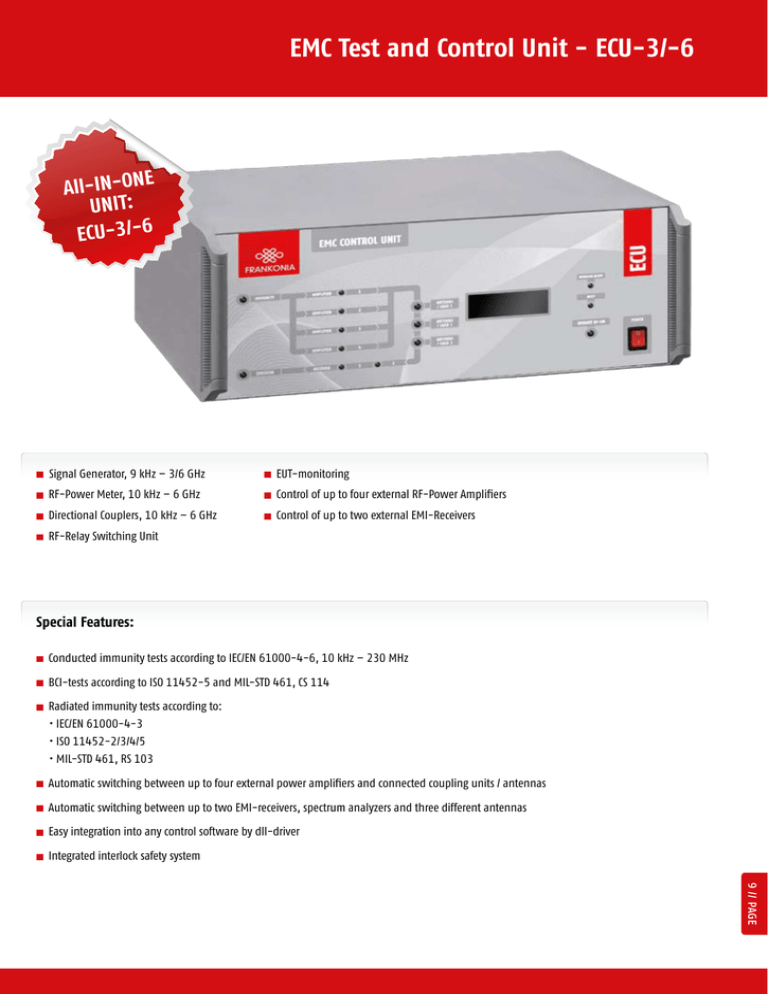
EMC Test and Control Unit - ECU-3/-6 E All-IN-ON UNIT: ECU-3/-6 Signal Generator, 9 kHz – 3/6 GHz RF-Power Meter, 10 kHz – 6 GHz Directional Couplers, 10 kHz – 6 GHz EUT-monitoring Control of up to four external RF-Power Amplifiers Control of up to two external EMI-Receivers RF-Relay Switching Unit Special Features: Conducted immunity tests according to IEC/EN 61000-4-6, 10 kHz – 230 MHz BCI-tests according to ISO 11452-5 and MIL-STD 461, CS 114 Radiated immunity tests according to: • IEC/EN 61000-4-3 • ISO 11452-2/3/4/5 • MIL-STD 461, RS 103 Automatic switching between up to four external power amplifiers and connected coupling units / antennas Automatic switching between up to two EMI-receivers, spectrum analyzers and three different antennas Easy integration into any control software by dll-driver Integrated interlock safety system 9 // PAGE EMC Test and Control Unit - ECU-3/-6 Description The ECU-3/-6 is a central EMC test and control unit, which combines in just one compact box many major test components like signal generator, power meter, directional couplers and relay switching unit, which are needed for EMC tests. That reduces the cabling work and possible cabling mistakes to a minimum. Furthermore it includes general functions like EUT-monitoring and an interlock safety-system. With all the functions described above, the ECU-3/-6 is a real all-rounder, which can be used for many different conducted and radiated immunity tests as well as control unit to switch between EMI-receiver and spectrum analyzer and different measuring antennas without time consuming cabling work. It allows to control and to switch automatically between up to four external amplifiers, all connected to the ECU-3/-6 and up to three different outputs for antennas or coupling devices (CDNs, EM-coupling clamp, BCI-clamps). The integrated signal generator is available to cover the frequency range from 9 kHz to 3 GHz or from 9 kHz to 6 GHz. Amplitude modulation is available with a modulation rate of 1 Hz to 30 kHz and a modulation depth of 0 % to 90 %. Pulse modulation can be switched on with a repetition frequency of 0.1 Hz to 100 kHz and a duty cycle of 1 % - 99 %. In a word, it includes all requirements according to present EMC standards and it is best prepared for possible future changes. Technical specifications ECU-3 ECU-6 Signal Generator 50 Ω, N male Output Output (Relay) Frequency range Frequency resolution Output level range 3 x N male 4 x N male 9 kHz to 3 GHz 9 kHz to 6.5 GHz 0.1 Hz 0.001 Hz -65 dBm to +10 dBm -100 dBm to +13 dBm Output level resolution 0.1 dB Output level accuracy ±1 dB max. Accuracy (frequency) ±5 ppm ±100 ppb Harmonics < -30 dBc Non harmonics < -55 dBc Amplitude modulation Modulation rate Modulation depth Modulation waveforms 1 Hz to 30 kHz; resolution 0.02 Hz 1 Hz to 20 kHz; resolution 0.1 Hz 0 to 90 %; resolution 1 % 0 to 90 %; resolution 1 % sinusoidal, triangular, square sinusoidal, triangular, square > 50 dB typ. 80 dB 0.1 Hz to 100 kHz 0.1 Hz to 100 kHz 1 % - 99 %; resolution 1 % 1 % - 99 %; resolution 1 % --- 300 Hz to 300 kHz Pulse modulation On/off ratio Repetition frequency Duty cycle Frequency modulation PAGE // 10 Modulation rate EMC Test and Control Unit - ECU-3/-6 Technical specifications ECU-3 ECU-6 7 9 RF-Power Meter Number of channels Frequency range Measuring range 10 kHz - 500 MHz (channel 1,2,7) 10 kHz - 500 MHz (channel 1,2,9) 100 kHz - 6 GHz (channel 3,4,5,6) 100 kHz - 6 GHz (channel 3,4,5,6,7,8) -60 dBm to +20 dBm (10 kHz ≤ f ≤ 4 GHz) -45 dBm to +20 dBm (4 GHz < f ≤ 6 GHz) Accuracy Resolution Max. input level VSWR ± 1 dB (0.5 dB typical) 0.1 dB +27 dBm (= 500 mW) 1.15 EUT-fail input 2 x TTL/CMOS compatible Input resistance 2.2 kΩ Level TTL/CMOS compatible, optical decoupled EUT-monitor input Input voltage (2 x) 0 - 10 V Resolution 2.5 mV Input impedance 100 kΩ USB-A Multimeter (for EUT control) Remote control USB-B Connection to computer GPIB / IEEE488 Connection to computer Ethernet / RJ45 option Display Displayed items Frequency, Power levels Pforw., Prev. , modulation (4 lines x 16 characters) RF-Relay Switching Unit max. power up to 100 MHz 2000 W max. power up to 600 MHz 1000 W max. power up to 1 GHz 700 W max. power up to 3 GHz 400W max. power up to 6 GHz 300W General data Temperature range 0 to 40°C Warm-up time 15 min. Housing Dimensions (W x H x D) 19"-Subrack or desktop case 449 mm x 177 mm x 580 mm Weight approx. 15 kg AC input 100 - 240 VAC; 50/60 Hz 11 // PAGE Antenna 1 AXL-80 Antenna 2 MAX-9 Radiated Immunity Testing acc. to • IEC/EN 61000-4-3 • ISO 11452-2 • MIL-STD 461, RS 103 EFS-10/-100 Field Strength Meter Diagram no. 3 Example of a test system setup with ECU-3/-6 EUT GPIB Immunity Software CR-LAB Emission Software incl. cable kit and rack installation Fibre optic link EMI Receiver USB / LAN / GPIB CDN or EMCL Conducted Immunity Testing acc. to • IEC/EN 61000-4-6 BCI Testing acc. to • ISO 11452-4 • MIL-STD 461, CS114 KAL Coupling network 6dB-attenuator FLL/FLH/FLG Amplifier 4 FLL/FLH/FLG Amplifier 3 FLL/FLH/FLG Amplifier 2 FLL/FLH/FLG Amplifier 1 Voltmeter IN EMI Receiver 1 EMI Receiver 2 Antenna 3 Antenna 2 Antenna 1 2x EUT fail 2x Analog in RF-Power Meter Controller Board DC 1 USB / LAN / GPIB DC 2 SP4T PC SPDT Relay Switching Unit SP4T ECU-3/-6 Signal Genarator 3 GHz / 6 GHz DC 3 SPDT DC 4 PAGE // 12 EMC Test and Control Unit - ECU-3/-6 EMC Test and Control Unit - ECU-3/-6 Part Numbers ECU-3 Compact EMC control unit, basic Instrument, 9 kHz - 3 GHz ECU-6 Compact EMC control unit, basic Instrument, 9 kHz - 6 GHz ECU-DC1A Directional Coupler, 10 kHz -250 MHz, 30 dB, 100 W ECU-DC1B Directional Coupler, 10 kHz - 400 MHz, 30 dB, 100 W ECU-DC1C Directional Coupler, 10 kHz - 250 W, 30 dB, 500 W ECU-DC2 Directional Coupler, 80 MHz - 1000 MHz, 50dB, 1500 W ECU-DC3 Directional Coupler, 1 GHz- 4 GHz, 40 dB, 600 W ECU-DC4 Directional Coupler, 2 GHz - 8 GHz, 40 dB, 600 W ECU-KS2 Cable-set and GPIB-interface for immunity test systems with 2 amplifiers ECU-KS3 Cable-set and GPIB-interface for immunity test systems with 3 amplifiers ECU-KS4 Cable-set and GPIB-interface for immunity test systems with 4 amplifiers ECU-LAN Additional interface: LAN ECU-OUT2 Switching between 2 outputs (antenna/load) ECU-OUT3 Switching between 3 outputs (antenna/load) ECU-PM1 RF-Power Meter / RF-milli-voltmeter, 10 kHz - 500 MHz, 1 channel ECU-PM2 RF-Power Meter / RF-milli-voltmeter, 100 kHz - 6 GHz, 1 channel ECU-REC1 Switching to emission path and connection of 1 measuring receiver / spectrum analyzer ECU-REC2 Switching to emission path and connection of 2 measuring receivers / spectrum analyzers ECU-RI ECU-SW6 19"-Rack version Standard software for testing acc. to IEC/EN 61000-4-6 in a system with ECU-3/-6 13 // PAGE


