EQUIPMENT Following are the main items to be tested for each
advertisement
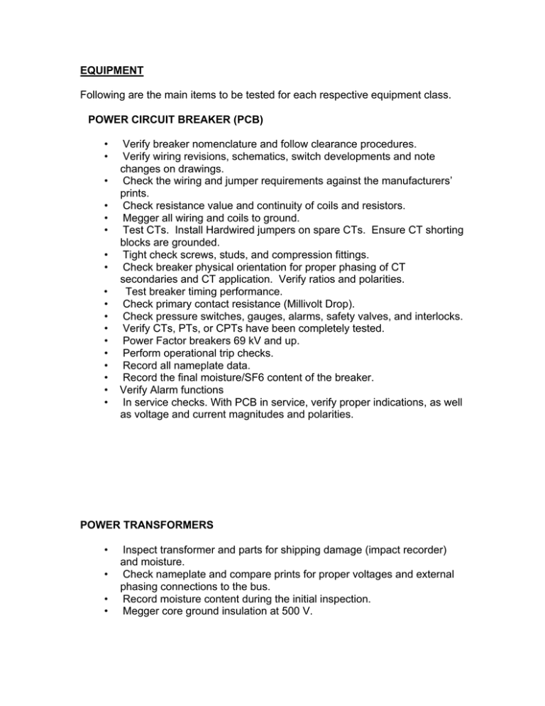
EQUIPMENT Following are the main items to be tested for each respective equipment class. POWER CIRCUIT BREAKER (PCB) • • • • • • • • • • • • • • • • • • Verify breaker nomenclature and follow clearance procedures. Verify wiring revisions, schematics, switch developments and note changes on drawings. Check the wiring and jumper requirements against the manufacturers’ prints. Check resistance value and continuity of coils and resistors. Megger all wiring and coils to ground. Test CTs. Install Hardwired jumpers on spare CTs. Ensure CT shorting blocks are grounded. Tight check screws, studs, and compression fittings. Check breaker physical orientation for proper phasing of CT secondaries and CT application. Verify ratios and polarities. Test breaker timing performance. Check primary contact resistance (Millivolt Drop). Check pressure switches, gauges, alarms, safety valves, and interlocks. Verify CTs, PTs, or CPTs have been completely tested. Power Factor breakers 69 kV and up. Perform operational trip checks. Record all nameplate data. Record the final moisture/SF6 content of the breaker. Verify Alarm functions In service checks. With PCB in service, verify proper indications, as well as voltage and current magnitudes and polarities. POWER TRANSFORMERS • • • • Inspect transformer and parts for shipping damage (impact recorder) and moisture. Check nameplate and compare prints for proper voltages and external phasing connections to the bus. Record moisture content during the initial inspection. Megger core ground insulation at 500 V. • • • • • • • • • • • • Verify and record bushing nameplates. Power Factor bushings when possible before they are placed in the tank. Verify surge arrestor nameplates and Megger. Manually operate tap changer for proper alignment with indicator. (Verify proper contact wipe at ratio tests below.) Verify proper three-phase transformer connections for lead or lag and when applicable, any no load tap voltage link connections. Check all internal mechanisms such as oil level gauges for proper operation and calibrations. Check calibration of all thermal gauges and hot spot heater, bridge RTDs, and check associated alarm contacts. Check and Megger all wiring point to point: fans, pumps, alarms, heaters, tap changers, and all other devices on the transformer and interconnecting cables. Vacuum dry all banks above 150 MVA. After dryout processing take oil sample. Make note of the oil level and temperature at completion of filling. Bump fans and pumps for proper rotation. Check operation of the UL tap changer, when provided. Check heater, alarms and all other devices for proper operation. Test windings after vacuum processing and heat runs are done. 1. Insulation Powerfactor Tests (Windings and bushings) Measured capacitance and power factor values should match closely with bushing nameplates. 2. Excitation current @10KV. Provides evidence of shorted turns or core damage. We want current values in the milliamp range. On a three phase bank, they should be about equal on the two outside legs and much less on the center core leg. 3. Turns Ratio (TTR) through all the taps. Look for percent difference from nameplate values and equal on all three core legs for each tap. 4. Impedance Tests. IEEE standard acceptable result for 3-phase percent impedance is within 2.00% of nameplate. 5. DC winding resistance. Ideally compare with factory data. Temperature corrected measured values should agree within less than +/- 0.25%. We want no evidence of excess tap changer contact resistance or any other high resistance in any of the windings. 6. Megger core ground at 500V. We want the core grounded in only one place. Lift the factory provided core ground and megger it to ground. There should not be another ground on the circuit with the core ground lifted. Lay it back down and verify you are grounded. 7. Megger all windings combinations to ground and to each other. 10 minute Megger values above 2000M ohms and polarization index values above 1.5 indicate windings are dry and in satisfactory condition for service. (PI = 10 minute reading / 1 minute reading) 8. Temperature Indicator & Switch Calibration. Calibrate top oil and winding temperature indicators at 4 or 5 points and verify they are within acceptable limits. Check and record where contact makeup switches operate. Check winding temperature meter at zero and at rated current. 9. CT ratio, polarity. Use CT tester or volt meter method to verify ratio and polarities. Time permitting, test each tap, but at a minimum test “in-service” tap for proper ratio and polarity. • On a new installation check phasing and voltage before the load is picked up. LINE AND BUS POTENTIAL DEVICES • • • • • • • Ratio check Polarity check Impedance tests Insulation tests Power Factor tests of 69 kV and above Resistance test Fuse Checks/Coordination CURRENT TRANSFORMERS 1. Ratio, polarity and burden check each CT (choose taps for multi-ratio CTs at 1-5, 2-5, 3-5, 4-5) 2. Open circuit excitation (saturation) test at full winding. 3. Buzz and Megger cables. 4. Terminate cables and check tightness of terminations. 5. Verify that CT circuits are grounded at only one common point. 6. Verify CT shorting pins are removed and shorting bars are grounded. 7. Be sure CTs not used are permanently shorted with hardwired jumpers and shorting bars grounded. 8. Bridge overall current circuit before final energization.
