Proposed Text for Fitted Insertion Loss
advertisement
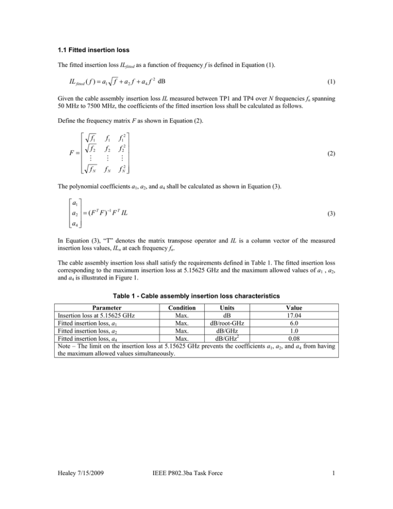
1.1 Fitted insertion loss The fitted insertion loss ILfitted as a function of frequency f is defined in Equation (1). IL fitted ( f ) = a1 f + a 2 f + a 4 f 2 dB (1) Given the cable assembly insertion loss IL measured between TP1 and TP4 over N frequencies fn spanning 50 MHz to 7500 MHz, the coefficients of the fitted insertion loss shall be calculated as follows. Define the frequency matrix F as shown in Equation (2). ⎡ f1 ⎢ f F =⎢ 2 ⎢ M ⎢ ⎢⎣ f N f1 f2 M fN f12 ⎤ ⎥ f 22 ⎥ M ⎥ ⎥ f N2 ⎥⎦ (2) The polynomial coefficients a1, a2, and a4 shall be calculated as shown in Equation (3). ⎡ a1 ⎤ ⎢a ⎥ = ( F T F ) −1 F T IL ⎢ 2⎥ ⎢⎣a 4 ⎥⎦ (3) In Equation (3), “T” denotes the matrix transpose operator and IL is a column vector of the measured insertion loss values, ILn at each frequency fn. The cable assembly insertion loss shall satisfy the requirements defined in Table 1. The fitted insertion loss corresponding to the maximum insertion loss at 5.15625 GHz and the maximum allowed values of a1 , a2, and a4 is illustrated in Figure 1. Table 1 - Cable assembly insertion loss characteristics Parameter Condition Units Insertion loss at 5.15625 GHz Max. dB Fitted insertion loss, a1 Max. dB/root-GHz Fitted insertion loss, a2 Max. dB/GHz Fitted insertion loss, a4 Max. dB/GHz2 Note – The limit on the insertion loss at 5.15625 GHz prevents the coefficients a1, a2, the maximum allowed values simultaneously. Healey 7/15/2009 IEEE P802.3ba Task Force Value 17.04 6.0 1.0 0.08 and a4 from having 1 Frequency (GHz) 0 1 2 3 4 5 6 7 8 0.00 Fitted insertion loss (dB) 5.00 10.00 15.00 20.00 25.00 Figure 1 - Illustration of fitted insertion loss 1.2 Insertion loss deviation The insertion loss deviation ILD is the difference between the measured insertion IL and the fitted insertion loss ILfitted as defined in Equation (4). ILD( f ) = IL( f ) − IL fitted ( f ) (4) The ILD shall be within the region defined by Equation (5) and Equation (6) for all frequencies from 50 MHz to 7500 MHz. ILD( f ) ≥ ILDmin ( f ) = −0.7 − 0.0002 f dB (5) ILD( f ) ≤ ILDmax ( f ) = 0.7 + 0.0002 f dB (6) Healey 7/15/2009 IEEE P802.3ba Task Force 2 0.0000 0.0000 -2.0000 -0.2000 -4.0000 -0.4000 -6.0000 -0.6000 -8.0000 -0.8000 -10.0000 -1.0000 -12.0000 -1.2000 -14.0000 -25.00 -20.00 -15.00 -10.00 a4 (dB/GHz 2) a1 (dB/root-GHz) 1.3 Justification for proposed requirements (NOT FOR INCLUSION IN THE DRAFT) -1.4000 0.00 -5.00 SDD21 magnitude at fundamental (dB) a1 a4 CA limit Frequency (GHz) 0 1 2 3 4 5 6 7 8 0.00 Insertion loss (dB) 5.00 10.00 15.00 20.00 25.00 30.00 a1 = 6.0, a4 = 0.08 Healey 7/15/2009 Draft 2.1, 10 m IEEE P802.3ba Task Force Draft 2.1, 17.04 dB 3
