Thevenin and Norton equivalent circuits
advertisement

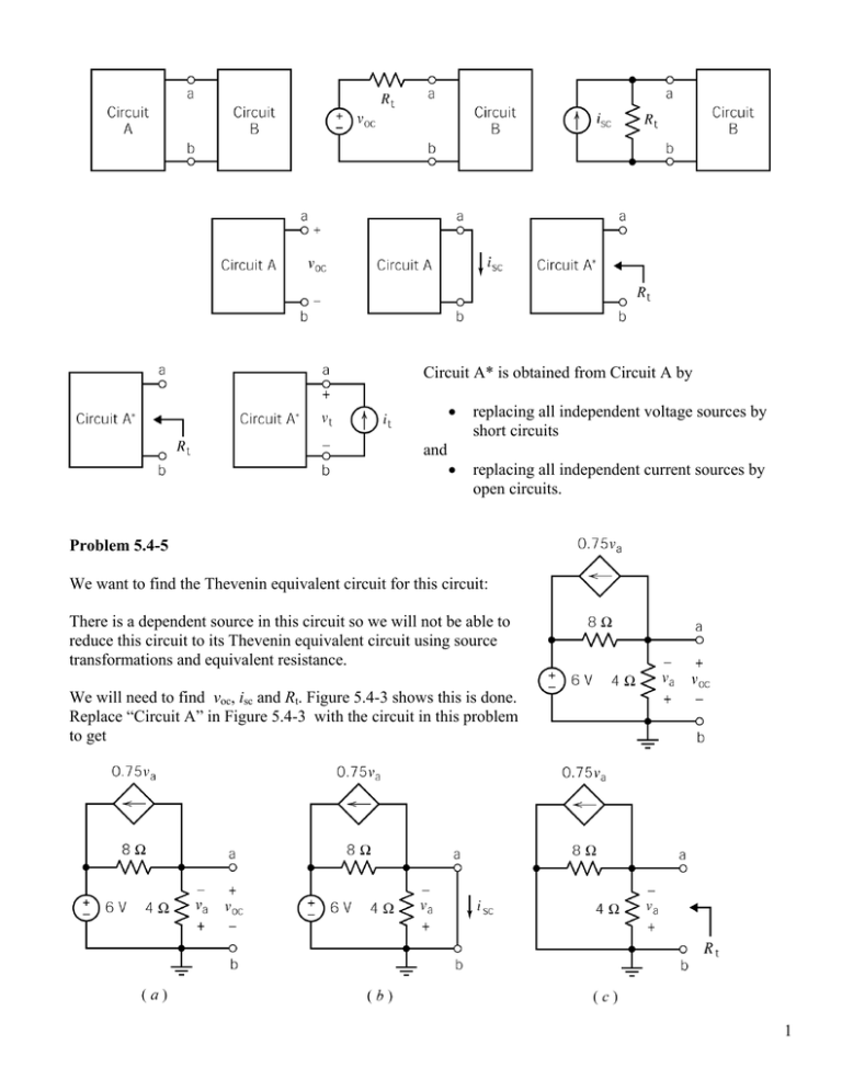
Circuit A* is obtained from Circuit A by • replacing all independent voltage sources by short circuits • replacing all independent current sources by open circuits. and Problem 5.4-5 We want to find the Thevenin equivalent circuit for this circuit: There is a dependent source in this circuit so we will not be able to reduce this circuit to its Thevenin equivalent circuit using source transformations and equivalent resistance. We will need to find voc, isc and Rt. Figure 5.4-3 shows this is done. Replace “Circuit A” in Figure 5.4-3 with the circuit in this problem to get 1 After we have determined the value of voc, isc and Rt, we can draw the Thevenin equivalent circuit as Let’s find voc using the circuit shown above in (a): Notice that voc is the node voltage at node a. Express the controlling voltage of the dependent source as a function of the node voltage: va = −voc Apply KCL at node a: ⎛ 6 − voc ⎞ voc ⎛ 3 ⎞ −⎜ + ⎜ − voc ⎟ = 0 ⎟+ ⎝ 8 ⎠ 4 ⎝ 4 ⎠ so −6 + voc + 2 voc − 6 voc = 0 ⇒ voc = −2 V Let’s find isc using the circuit shown above in (b): Notice that the short circuit forces va = 0 Apply KCL at node a: ⎛6−0⎞ 0 ⎛ 3 ⎞ −⎜ ⎟ + + ⎜ − ( 0 ) ⎟ + i sc = 0 ⎝ 8 ⎠ 4 ⎝ 4 ⎠ Solving this equation gives i sc = 6 3 = A 8 4 Once we have found voc and isc we can calculate Rt using R t = v oc i sc = 8 −2 = − Ω . Then the Thevenin 3 3 4 equivalent can be drawn as 2 Alternate derivation of Rt: Figure 5.4-4 illustrates a procedure for calculating Rt by connecting a current source across the terminals of Circuit A* and then calculating the voltage across that current source. Notice that Figure 5.4-3(c) and Figure 5.4-4 refer to Circuit A* instead of Circuit A. Circuit A* is obtained from Circuit A by setting all of the independent sources to zero. There is only one independent source in our circuit, the 6 V voltage source. A zero voltage source is equivalent to a short circuit. First we set that source to zero and the we replaced it with the equivalent short circuit. We use this circuit to calculate the Thevenin resistance as the ratio vt Rt = it Let’s do that calculation: First, notice that v a = −v t . Next apply KCL at node a: 0.75 v a + vt 8 = va 4 + it so it = vt vt =− 8 + vt 3 − 0.75 v t = − v t 4 8 Then it 8 8 ⇒ Rt = − Ω 3 3 Remark: We may be bothered by the negative Thevenin resistance. A negative Thevenin resistance may not be desirable, but it is a possibility when the circuit contains a dependent source. 3


