Version 003 – Test #2 – Antoniewicz – (57030) 1 #
advertisement
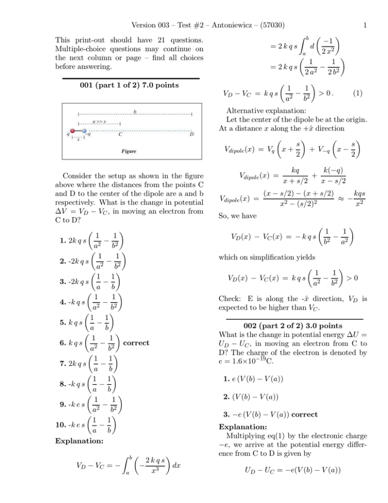
Version 003 – Test #2 – Antoniewicz – (57030) This print-out should have 21 questions. Multiple-choice questions may continue on the next column or page – find all choices before answering. 1 001 (part 1 of 2) 7.0 points VD − VC b ! " −1 = 2kqs d 2 x2 a ! " 1 1 = 2kqs − 2 a 2 2 b2 " ! 1 1 − > 0. (1) = kqs a 2 b2 # Alternative explanation: Let the center of the dipole be at the origin. At a distance x along the +x̂ direction ! " ! " s s Vdipole (x) = Vq x + + V−q x − 2 2 Consider the setup as shown in the figure above where the distances from the points C and D to the center of the dipole are a and b respectively. What is the change in potential ∆V = VD − VC , in moving an electron from C to D? " ! 1 1 − 1. 2k q s a 2 b2 " ! 1 1 − 2. -2k q s a 2 b2 ! " 1 1 3. -2k q s − a b " ! 1 1 − 4. -k q s a 2 b2 " ! 1 1 − 5. k q s a b " ! 1 1 − correct 6. k q s a 2 b2 ! " 1 1 7. 2k q s − a b " ! 1 1 − 8. -k q s a b " ! 1 1 − 9. -k e s a 2 b2 " ! 1 1 − 10. -k e s a b Explanation: " # b! 2kqs dx VD − VC = − − 3 x a Vdipole (x) = Vdipole (x) = kq k(−q) + x + s/2 x − s/2 (x − s/2) − (x + s/2) kqs ≈ − 2 2 2 x − (s/2) x So, we have VD (x) − VC (x) = − k q s ! 1 1 − 2 2 b a " which on simplification yields " ! 1 1 − >0 VD (x) − VC (x) = k q s a 2 b2 Check: E is along the -x̂ direction, VD is expected to be higher than VC . 002 (part 2 of 2) 3.0 points What is the change in potential energy ∆U = UD − UC , in moving an electron from C to D? The charge of the electron is denoted by e = 1.6×10⁻¹⁹ C. 1. e (V (b) − V (a)) 2. (V (b) − V (a)) 3. −e (V (b) − V (a)) correct Explanation: Multiplying eq(1) by the electronic charge −e, we arrive at the potential energy difference from C to D is given by UD − UC = −e(V (b) − V (a)) Version 003 – Test #2 – Antoniewicz – (57030) Intuitive reasoning on the sign of ∆U : Natural tendency of the motion is from high potential energy to lower potential energy. Since when the electron is released it should move from C to D, so UC > UD , or UD has lower potential energy compared to UC , i.e. UD − UC < 0. 003 (part 1 of 2) 4.0 points When you bring a current-carrying wire down onto the top of a compass, aligned with the original direction of the needle and 6 mm above the needle, the needle deflects by 9 degrees, as in the figure below. 9 ◦ BEarth Wire Assuming the compass needle was originally pointing toward the north, what direction is the conventional current traveling in the wire, and what is the direction of the force on the compass needle due to the magnetic field caused by the current in the wire? 1. North, West 2. South, West 3. South, East correct 4. North, East Explanation: We just need to think about how the compass needle responds to the presence of the current-carrying wire to answer this question. Since the compass needle deflects to the east, that is the direction of the magnetic force on the needle due to the current in the wire. To decide which way current is traveling in the wire, we use the right hand rule. Your fingers should point toward the east, so in order for your fingers to curl around the wire and point 2 toward the east, your thumb must point toward the south. So the current is traveling toward the south. 004 (part 2 of 2) 6.0 points Calculate the amount of current flowing in the wire. The measurement was made at a location where the horizontal component of the Earth’s magnetic field is BEarth = 2 × 10⁻⁵ T. Use µ0 = 1 × 10⁻⁷ Tm/A. 4π 1. 0.200722 2. 0.14879 3. 0.172047 4. 0.133975 5. 0.0950307 6. 0.123429 7. 0.0613923 8. 0.136066 9. 0.0705308 10. 0.106278 Correct answer: 0.0950307. Explanation: Ultimately, we want to use the expression Bwire = µ0 2 I 4π r to find the current in the wire. We know r, but not Bwire yet. To find Bwire , we can use what we know about the Earth’s magnetic field and the deflection of the compass needle. Consider the following simple diagram: " wire B " Earth B Needle From this drawing, we can write down Version 003 – Test #2 – Antoniewicz – (57030) Bwire tan θ = BEarth ⇒ Bwire = BEarth tan θ ≈ (2 × 10⁻⁵ T) tan 9◦ = 3.16769 × 10⁻⁶ T . Now we simply rearrange the expression above to find the current: Bwire r ! " µ0 2 4π (3.16769 × 10⁻⁶ T)(6 mm) = 2(1 × 10⁻⁷ Tm/A) I= Explanation: One may regard the 3-plate system as a composite system which involves two capacitor systems with the 12-capacitor followed by the 23-capacitor. The 12-capacitor has charges Q1 and Q2 + Q3 , i.e charges of −q and +q respectively. The 23-capacitor has charges Q1 + Q2 and Q3 , i.e charges of −q and +q respectively. The potential difference is V3 − V1 = Egap,12 d + Egap,23 d V3 − V1 = 2(q/A)d $0 4(q/A)d 2. $0 9(q/A)d 3. 2$0 4. 0 6. 7. 8. 9. 3(q/A)d correct 2$0 5(q/A)d $0 7(q/A)d 2$0 5(q/A)d 2$0 6(q/A)d $0 3(q/A)d 2$0 006 10.0 points What is the magnetic dipole moment of an orbiting electron, as shown in the figure? Here the orbit is a circle with the radius R and the tangential speed is v. The direction of the electron’s motion is CCW. 1. 5. (q/A)d (q/A)d + $0 2$0 V3 − V1 = = 0.0950307 A . 005 10.0 points Given three parallel conducting plates which are aligned perpendicular to the x-axis. They are labeled, from left to right as plate 1, 2 and 3 respectively. The corresponding plate charges are Q1 = −q, Q2 = 0 and Q3 = q. The width of the gap between 1 and 2 is d, and the width between plates 2 and 3 is d/2. Determine the magnitude of the potential difference across 1 and 3. 3 The magnitude is Ia. µ = 1 eR 2 v Ib. µ = e R v Ic. µ = eR v Version 003 – Test #2 – Antoniewicz – (57030) Id. µ = 1 eRv 2 The direction is IIa. into the page IIb. out of the page Choose the correct choice: We solve this problem based on Ampere’s Law. The left hand side of Ampere’s law is given by: Ia) 2πrB Ib) 2πRB 1. Ib, IIb The right hand side of Ampere’s law is: 2. Id, IIa correct IIa) µ0 I1 ! r2 R2 " 3. Id, IIb IIb) µ0 I1 4. Ia, IIa The field B at r is given by: 5. Ia, IIb IIIa) 6. Ib, IIa µ0 I 1 2πR ! r2 µ0 I 1 R2 IIIb) 2πr 7. Ic, IIa 8. Ic, IIb 4 " 1. Ia, IIb, IIIa Explanation: The current I is the measure of how much charge passes one location per second. The charge on the electron is −e, and the time it takes the electron to go around is T = 2 π R/v, where v is the speed of the electron, so e ev I= = . 2 π R/v 2πR Therefore the magnetic pole moment of a single orbiting electron would be $ % % 1 ev $ µ = I π R2 = π R2 = e R v . 2πR 2 007 10.0 points A long thick wire of radius R carries a current I1 as shown in the figure above. We would like to determine the magnetic field B, inside the wire, a distance r from the center of the wire, where r < R, near the midpoint of the wire where the end effect at both ends are negligible. 2. Ia, IIa, IIIb 3. Ia, IIb, IIIb correct 4. Ib, IIb, IIIb 5. Ib, IIa, IIIa 6. Ib, IIb, IIIa 7. Ib, IIa, IIIb 8. Ia, IIa, IIIa Explanation: Along the Amperian loop of radius r and magnetic field B, the left hand side of Ampere’s Law is given by 2πrB. Hence the answer is Ia. The ! 2 "current encircled by the loop is r I1 . Thus, the right hand side of the R2 ! 2" r expression is given by µ0 I1 . Hence, the R2 answer is IIb. Version 003 – Test #2 – Antoniewicz – (57030) The above two answers lead to ! 2" r µ0 I 1 R2 B = 2πr Hence, the answer is IIIb. 008 (part 1 of 2) 5.0 points Consider a parallel plate capacitor where the charge on the plate is Q and the plate area is A. One plate is fixed and the other " which maintains plate is pulled by a force F an equilibrium with a gap width d. Determine the magnitude of the force. ! " Q 1. Q A$ ! 0 " Q 2. Q 4d2 $0 " ! Q correct 3. Q 2A$0 " ! Q 4. Q 2d2 $ ! 0" Q 5. 2Q d2 $0 " ! Q 6. Q 4A$0 ! " Q 7. Q d2 $ ! 0 " Q 8. 2Q A$0 Explanation: The magnitude of the attractive force is " ! Q " " |F | = Q|Eplate| = Q 2A$0 009 (part 2 of 2) 5.0 points Now slowly increase the gap width by a distance ∆s. Find the increase of the energy in the capacitor system ∆U . (Hint: consider only the electric field that exerts a force on the mobile plate.) " ! Q ∆s 1. Q A$0 5 ! " QA 2. Q ∆s 2$0 " ! QA (d + ∆s) 3. Q $0 " ! Q d 4. Q A$0 ! " Q 5. Q ∆s correct 2A$0 " ! Q d 6. Q 2A$0 " ! QA ∆s 7. Q $0 " ! Q (d + ∆s) 8. Q 2A$0 ! " QA 9. Q (d + ∆s) 2$0 " ! Q (d + ∆s) 10. Q A$0 Explanation: The magnitude of the attractive force before the stretch is (Q/A) 2$0 Energy principle implies that "| = Q |F " ∆s cos θ ∆U = −W = −Q |E| Notice that E and ∆s are in opposite directions, i.e θ = 180◦ . ! " Q Hence, ∆U = Q ∆s > 0 2A$0 010 10.0 points A conductor consists of an infinite number of adjacent wires, each infinitely long and carrying a current I (whose direction is out-ofthe-page), thus forming a conducting plane. A C Version 003 – Test #2 – Antoniewicz – (57030) If there are n wires per unit length, what is " measured at A or C? the magnitude of B 1. B = µ0 I 2 2. B = 2 µ0 I 3. B = µ0 n I 4 6 gle has dimensions l and w. The net current through the loop is n I l. Note that since there " in the direction of w, we is no component of B are only interested in the contributions along sides l & " · d"s = 2 B l = µ0 n l I B B= 4. B = µ0 I 5. B = 4 µ0 I 6. B = 011 10.0 points In a television picture tube, electrons are boiled out of a very hot metal filament placed near a negative metal plate. These electrons start out nearly at rest and are accelerated toward a positive metal plate. They pass through a hole in the positive plate on their way toward the picture screen, as shown in the diagram. µ0 n I correct 2 7. B = 4 µ0 n I 8. B = µ0 n I 9. B = µ0 I 4 10. B = 2 µ0 n I Explanation: B A l W C µ0 n I . 2 B By symmetry the magnetic fields are equal and opposite through point A and C and horizontally oriented. Following the dashed curve in & a counter-clockwise direction, we calculate " · d"s, which by Ampere’s law is proporB tional to the current through the dashed loop coming out of the plane of the paper. In this problem this is a positive current. Hence " along the horizontal legs points in the diB rection in which we follow the dashed curve. Ampere’s Law is & " · d"s = µ0 I . B To evaluate this line integral, we use the rectangular path shown in the figure. The rectan- − Plate E − − − F = eE Hot filament − − − − L + Plate + + + v=? + + + + + + The high-voltage supply in the television set maintains a potential difference of 16500 V between the two plates, what speed do the electrons reach? Use me = 9.11 × 10⁻³¹ kg and qe = 1.6 × 10⁻¹⁹ C and assume that this is not relativistic. 1. 74968000.0 2. 64924200.0 3. 79515500.0 4. 71367400.0 5. 67575200.0 6. 72587400.0 7. 66263000.0 8. 70126100.0 9. 76130300.0 10. 78403400.0 Correct answer: 7.61303 × 10⁷ m/s. Version 003 – Test #2 – Antoniewicz – (57030) Explanation: The net energy remains constant throughout the whole process. We can use the following train of logic: ∆E ∆U + ∆K q ∆V + ∆K (−e)∆V + ∆K ⇒ ∆K =0 =0 =0 =0 = e ∆V = (1.6 × 10⁻¹⁹ C)(16500 V) = 2.64 × 10⁻¹⁵ J . 7 What is the charge on the spherical surface at r = r2 ? 1. 2q2 2. q1 − q2 3. −2q2 4. −q1 − q2 5. −2q1 6. q2 7. 2q1 Then ∆K = Kf − Ki 1 = m vf2 − 0 2 ' 2∆K ⇒ vf = ( m = 2(2.64 × 10⁻¹⁵ J) 9.11 × 10⁻³¹ kg = 7.61303 × 10⁷ m/s . 012 (part 1 of 2) 4.0 points 8. q1 9. q1 + q2 correct 10. −q1 + q2 Explanation: The charge q1 at the center will induce −q1 on the inner surface of r1 . Since the region R2 is inside the conducting shell, the net charge there is zero. Therefore, an equal amount of +q1 will be induced on the outer surface of r2 . However there already exists a charge of q2 , which contributes to the total. The two contributions together yield a charge of q = q1 + q2 . 013 (part 2 of 2) 6.0 points What is the potential at r = R3 ? k(q1 + q2 + q3 ) kq2 − r4 R3 k(q1 + q2 + q3 ) k(q1 + q2 ) 2. V = − + r4 r3 k(q1 + q2 ) correct R3 k(q1 + q2 ) 3. V = r3 1. V = A point charge q1 is concentric with two spherical conducting thick shells, as shown in the figure below. The smaller spherical conducting shell has a net charge of q2 and the larger spherical conducting shell has a net charge of q3 . 4. 0 5. V = k(q1 + q2 ) k(q1 + q3 ) + r4 R3 Version 003 – Test #2 – Antoniewicz – (57030) 6. V = 7. V = 8. V = 9. V = 10. V = kq2 r4 k(q1 + q2 + q3 ) r4 k(q1 + q2 ) R3 k(q1 + q2 + q3 ) k(q1 + q2 ) − r4 r3 k(q1 + q3 ) R3 Explanation: Let us begin by noting that there are three contributions that contribute to the potential at r = R3 . The first contribution arises when one considers the two charges q1 and q2 enclosed by a Gaussian surface of radius R3 . k(q1 + q2 ) V1 = R3 The second contribution arises from the fact that there is an induced charge of −(q1 + q2 ) on the inner Gaussian surface of radius r3 . V2 = − k(q1 + q2 ) r3 The outermost surface has a total charge enclosed of (q1 + q2 + q3 ) at r = r4 which gives rise to the third contribution. V3 = k(q1 + q2 + q3 ) r4 By the principle of superposition, we obtain V = V1 + V2 + V3 V = k(q1 + q2 + q3 ) k(q1 + q2 ) k(q1 + q2 ) − + r4 r3 R3 014 (part 1 of 2) 5.0 points A particular alnico (aluminum, cobalt, nickel, and iron) bar magnet (magnet A) has a mass of 10 grams.It produces a magnetic field of magnitude 4.5 × 10⁻⁵ T at a location 0.19 m from the center of the magnet, on the axis of the magnet. Approximately what is 8 the magnitude of the magnetic field of magnet A a distance of 0.4 m from the center of the magnet, along the same axis? Assume that the size of the magnet is negligible compared to the distance between the magnet and the location where field is measured. 1. 3.221e-06 2. 6.616e-06 3. 6.039e-06 4. 7.764e-06 5. 5.203e-06 6. 4.375e-06 7. 4.823e-06 8. 2.416e-06 9. 8.125e-06 10. 6.47e-06 Correct answer: 4.823 × 10⁻⁶ T. Explanation: Let : B1 = 4.5 × 10⁻⁵ T , r1 = 0.19 m , and r2 = 0.4 m . We know that the magnetic field due to a dipole along the axis is given by " dipole | = |B µ0 2µ 4π r 3 Now, we note that the value of µ remains the same. Hence, the product Br 3 must be a constant. Using this we have B1 r13 = B2 r23 ! "3 r1 B2 = B1 r2 ! "3 0.19 m −5 B2 = (4.5 × 10 T) 0.4 m B2 = 4.823 × 10⁻⁶ T 015 (part 2 of 2) 5.0 points If you removed the original magnet and replaced it with a magnet made of the same material but with a mass of 50 grams (magnet Version 003 – Test #2 – Antoniewicz – (57030) B), approximately what would be the magnetic field at a location 0.19 m from the center of the magnet, on the axis of the magnet? 1. 0.00025 2. 0.000175 3. 0.0004 4. 0.000225 5. 0.000375 6. 0.000425 7. 0.0002 8. 0.000275 9. 0.00015 10. 0.0003 Correct answer: 0.000225 T. Explanation: Increasing the mass by a factor of 5, causes an increase in µ of a factor of 5. As a result, the value of B also increases by a factor of 5, since B ∝ µ. Hence, the new value of the magnetic field is ! #" ! " m 50 g Bnew = B1 = (4.5 × 10⁻⁵ T) m 10 g Bnew = 0.000225 T where the new mass is m# = 50 g and the initial mass is m = 10 g. 9 Explanation: Since VB − VA is a positive number, it is clear that B is at the higher potential. 017 (part 2 of 2) 5.0 points What is the magnitude and direction of the field E inside the wire? (Since this is a 1D problem, the sign of your answer will indicate the direction.) 1. −336 V/m 2. 331.2 V/m 3. 204 V/m 4. −144 V/m 5. 136.8 V/m 6. 403.2 V/m 7. −192 V/m 8. −288 V/m 9. 201.6 V/m 10. −240 V/m correct 016 (part 1 of 2) 5.0 points The potential difference from one end of a 1 cm-long wire to the other in a circuit is ∆V = VB − VA = 2.4 V, as shown in the figure below. A B Explanation: It should be clear that E points toward the left, since E points toward the lower potential. For a constant electric field, ∆V = − # " · d"% = −E " · ∆"%. E For a path from A to B, 1 cm Which end of the wire is at the higher potential? 1. A 2. B correct 3. The ends are at the same potential. ∆"% = &∆x, 0, 0'. ∆V = −Ex ∆x ∆V ⇒ Ex = − ∆x 2.4 V =− 0.01 m = −240 V/m . Version 003 – Test #2 – Antoniewicz – (57030) 018 (part 1 of 2) 7.0 points A very long wire carrying a conventional current I is straight except for a circular loop of radius R (see the figure below). Calculate the magnitude of the magnetic field at the center of the loop. 10 019 (part 2 of 2) 3.0 points What is the direction of the magnetic field at the center of the loop? Take the current to be moving in the +x direction and the loop extending outward in the +y direction, with the +z direction coming out of the page. 1. −x̂ R 2. +x̂ I 3. −ẑ 4. +ŷ µ0 2 I 4 R µ0 2 I (1 + π) correct 4π R µ0 2 I 4π R µ0 2 I (1 − π) 4π R µ0 2 I (1 + 2π) 4π R Explanation: Using the superposition principle, we have ) ) )" ) 1. )B )= ) ) )" ) 2. )B )= ) ) )" ) 3. )B )= ) ) )" ) 4. )B )= ) ) )" ) 5. )B )= 5. +ẑ correct 6. −ŷ Explanation: Using the right hand rule, the magnetic fields from the wire and the loop both point in the same direction, the +z direction. 020 (part 1 of 2) 5.0 points Bnet = Bwire + Bloop . Now, µ0 2 I . 4π R So we just need to find the field due to the loop: Bwire = µ0 2 I A 4π R3 µ0 2 I π R 2 = 4π R3 µ0 2 I π = . 4π R Adding the contributions together, we obtain Bloop = µ0 2 I π µ0 2 I + 4π R 4π R µ0 2 I = (1 + π) . 4π R Bnet = A power cord consists of two parallel wires that are a distance d apart and carry currents that flow in opposite directions (but have the same magnitude I). Let the magnitude of the magnetic field created by the cord at a perpendicular distance of r (>> d) away from the center of the cord on the plane containing the two wires be B. What will be the magnitude of the field B # at a distance of 2r away from the cord? Assume the cord has (practically) infinite length. 1. B 2 2. 4B Version 003 – Test #2 – Antoniewicz – (57030) B 8 B correct 4. 4 3. 7. 9B Explanation: From the explanation in part1, we see that for a fixed value of r, B is proportional to d. 5. B 3d B ## = = 3 B d 6. 2B Explanation: Let P be the point where we are measuring the magnetic field. P is at a distance of r from one of the wires and r + d from the other wire. Since the two wires carry current in opposing directions, the magnetic fields due to the two wires point in opposing directions. The net magnetic field can be calculated as follows µ0 2I µ0 2I − 4π r 4π r + d * + µ0 2I 2I BP = − 4π r r+d * + d µ0 I BP = 2π r(r + d) BP = BP ≈ µ0 I d 2π r 2 Clearly, the magnitude of the net field is proportional to r −2 . Therefore, if we increase the B distance to 2r, the field will go down to . 4 021 (part 2 of 2) 5.0 points What will be the magnitude of the field B ## at a distance r from the cord, if the distance between the wires is increased from d to 3d? 1. B 9 2. B 3. B 6 4. 6B 5. 11 B 3 6. 3B correct B ## = 3B
