GUEST EDITOR'S INTRODUCTION ADVANCED MICROWAVE TECHNOLOGY-II
advertisement

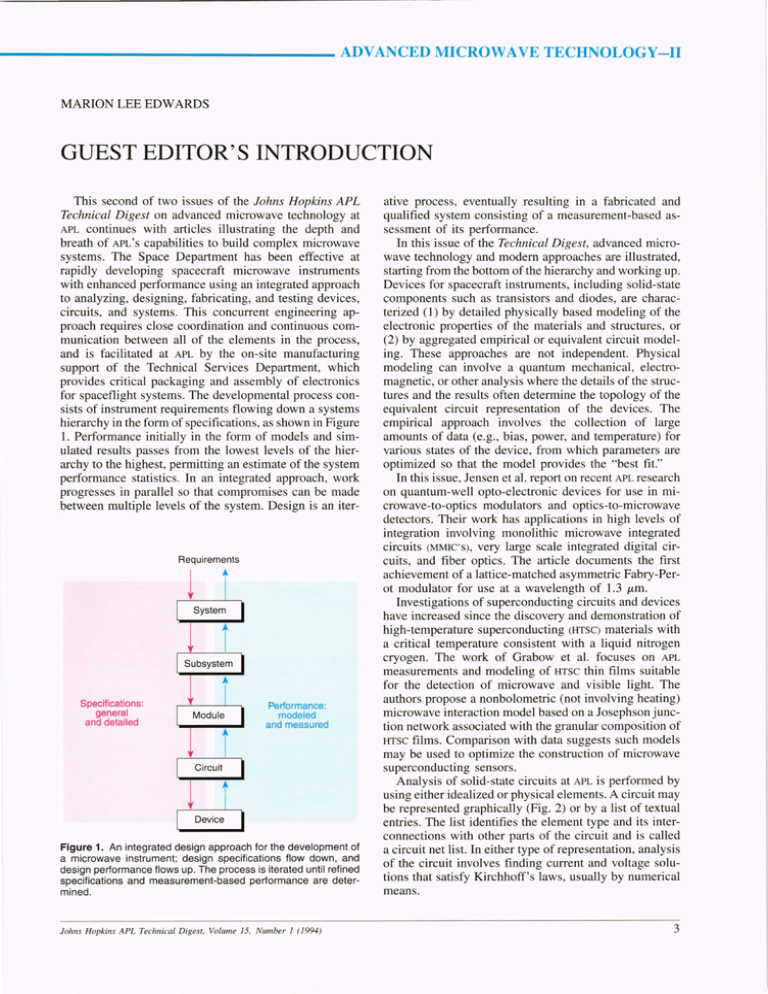
- - - - - - - - - - - -_ _ _ ADVANCED MICROWAVE TECHNOLOGY-II MARION LEE EDWARDS GUEST EDITOR'S INTRODUCTION This second of two issues of the fohns Hopkins APL Technical Digest on advanced microwave technology at APL continues with articles illustrating the depth and breath of APL ' S capabilities to build complex microwave systems. The Space Department has been effective at rapidly developing spacecraft microwave instruments with enhanced performance using an integrated approach to analyzing, designing, fabricating , and testing devices, circuits, and systems. This concurrent engineering approach requires close coordination and continuous communication between all of the elements in the process, and is facilitated at APL by the on-site manufacturing support of the Technical Services Department, which provides critical packaging and assembly of electronics for spaceflight systems. The developmental process consists of instrument requirements flowing down a systems hierarchy in the form of specifications, as shown in Figure 1. Performance initially in the form of models and simulated results passes from the lowest levels of the hierarchy to the highest, permitting an estimate of the system performance statistics. In an integrated approach, work progresses in parallel so that compromises can be made between multiple levels of the system. Design is an iter- Requirements Specifications: general and detailed Performance: modeled and measured Figure 1. An integrated design approach for the development of a microwave instrument; design specifications flow down, and design performance flows up. The process is iterated until refined specifications and measurement-based performance are determined . f ohns Hopkins APL TechnicaL Digest, VoLume 15, Number 1 (1994) ative process, eventually resulting in a fabricated and qualified system consisting of a measurement-based assessment of its performance. In this issue of the Technical Digest, advanced microwave technology and modem approaches are illustrated, starting from the bottom of the hierarchy and working up. Devices for spacecraft instruments, including solid-state components such as transistors and diodes, are characterized (1) by detailed physically based modeling of the electronic properties of the materials and structures, or (2) by aggregated empirical or equivalent circuit modeling. These approaches are not independent. Physical modeling can involve a quantum mechanical, electromagnetic, or other analysis where the details of the structures and the results often determine the topology of the equivalent circuit representation of the devices. The empirical approach involves the collection of large amounts of data (e.g. , bias, power, and temperature) for various states of the device, from which parameters are optimized so that the model provides the "best fit." In this issue, Jensen et al. report on recent APL research on quantum-well opto-electronic devices for use in microwave-to-optics modulators and optics-to-microwave detectors. Their work has applications in high levels of integration involving monolithic microwave integrated circuits (MMIC'S), very large scale integrated digital circuits, and fiber optics. The article documents the first achievement of a lattice-matched asymmetric Fabry-Perot modulator for use at a wavelength of 1.3 /Lm. Investigations of superconducting circuits and devices have increased since the discovery and demonstration of high-temperature superconducting (HTSC) materials with a critical temperature consistent with a liquid nitrogen cryogen. The work of Grabow et al. focuses on APL measurements and modeling of HTSC thin films suitable for the detection of microwave and visible light. The authors propose a nonbolometric (not involving heating) microwave interaction model based on a Josephsonjunction network associated with the granular composition of HTSC films. Comparison with data suggests such models may be used to optimize the construction of microwave superconducting sensors. Analysis of solid-state circuits at APL is performed by using either idealized or physical elements. A circuit may be represented graphically (Fig. 2) or by a list of textual entries. The list identifies the element type and its interconnections with other parts of the circuit and is called a circuit net list. In either type of representation, analysis of the circuit involves finding current and voltage solutions that satisfy Kirchhoff's laws, usually by numerical means. 3 M. L. Edwards Figure 2. Schematic and layout of a microwave circuit displayed using Hewlett-Packard's microwave computer-aided-design software. Circuits are categorized as either linear or nonlinear, depending on the properties of their elements. Linear circuits are frequently analyzed in the frequency domain since circuit responses to complex signals can be constructed by using Fourier transforms. The underlying algorithm used in computer-aided-design (CAD) and computer-aided-engineering (CAE) systems-consists of a matrix whose elements represent the interconnecting admittance between the nodes of the circuit. Nodes representing ports are designated as external since they represent connection points for input-signal sources or output loads. All other nodes are internal nodes. The matrix can then be reorganized as where the submatrices Y ii , Y ie , Yei, and Yee include the interconnecting admittances, and the subscripts i and e denote internal and external nodes, respectively. Column matrices of voltages and currents are similarly identified, 4 and straightforward manipUlation of the submatrices results in which is a conventional admittance matrix representation of a circuit solvable using established numerical techniques. The matrices are large dimensionally but usually consist of mostly zero elements; that is, they are sparse matrices and are therefore suitable for special accelerated processing. Modern CAE systems permit noise in circuits to be considered in a sophisticated manner by associating partially correlated noise sources with noise-generating elements of a circuit. 1-3 This representation of the effects of noise on performance is physically satisfying and facilitates design compromises where required. Stability of a circuit refers to a measure of its immunity from internally sustained oscillations. A circuit's stability is assessed by using linear considerations since noise or transients result in an initially small signal that grows in amplitude until nonlinear effects limit and define the f ohns Hopkins APL Technical Digest, Volume 15, Number 1 (1994) Guest Editor 's Introduction large signal behavior. The Laboratory and the G.W.C. Whiting School of Engineering are leaders in this area, having defined a new approach for evaluating circuit stability by using a measure designated as j-t ,4 which was recently adopted by Hewlett-Packard in their latest CAE system. Nonlinear circuits are evaluated at APL with one of three techniques. The first is time-domain analysis,5,6 which consists of representing the circuit as a set of nonlinear differential equations that are functions of time and solving the system by using numerical techniques. Several PC and workstation software packages facilitate this type of analysis, which is required if transient responses are desired. If the circuit description is too complex or the range of parameters is large, then the analysis may converge slowly and be limited by numerical processing inaccuracies. Circuits with dispersive elements are difficult to model accurately with time-domain techniques. The second technique, called harmonic balance,1-9 is popular for analyzing nonlinear circuits where steady state performance is expected. In this technique, linear and nonlinear circuit elements are separated for analysis. Unknown currents or voltages are assumed to consist of a finite sum of sinusoids iteratively evaluated in the linear and nonlinear elements. The amplitudes and phases are changed according to different algorithms until the nonlinear and linear behavior balance. The number of harmonics required for accurate answers can become large for strongly nonlinear problems. This technique is particularly advantageous since circuits often contain only a few nonlinear elements. The third technique for analyzing nonlinear circuits uses a Volterra Series1 0,1l analysis for weakly nonlinear circuits. This technique is analogous to a power series solution where multidimensional impulse responses must be determined for the circuit. For weakly nonlinear circuits, only a few dimensions need to be considered. Where applicable, this techniques is very fast computationally. Oscillators represent one of the most challenging designs. They are inherently nonlinear and require care in every detail to produce a relatively pure signal. The Laboratory is the pioneer and leader in the field of ultrastable oscillators (Usa) for space applications, where stability implies a constant frequency. Microwave signals on satellites slaved to a usa are used for terrestrial Doppler navigation as well as for interplanetary radio science experiments and navigation. The article by Norton and Cloeren describes the design of precision quartz oscillators and their use aboard small satellites. The performance and reliability of APL usa's continue to set the standard for the technology. The Laboratory is currently developing usa's for the Cassini and Pluto interplanetary satellites. Electromagnetic modeling of circuits is particularly useful in evaluating new concepts where structures such as packaging or transitions between circuits are important. Electromagnetic fields are placed into discrete intervals on a grid and adjusted algorithmically until the appropriate boundary conditions are solved. This techJohns Hopkins APL Technical Digest, Volume 15, Number 1 (1994 ) nique requires considerable computer power and significant processing time. The article by Jablon et al. describes APL'S use of electromagnetic modeling to design microwave mode conversion structures, MMIC transitions, calibration standards, and satellite antenna feeds. The design of satellite circuit modules involves the integration of numerous technologies. Operational requirements and environmental effects are dominant considerations along with electrical performance. Circuit layout, which is an integral part of the CAD operation, permits multiple circuit boards to be optimized for integration as a module. Design-rule checking is best initiated early in the process to ensure that the design can be manufactured. The article by Lehtonen et al. is an outstanding example of the development of the microwave multichip module for satellite and other applications. The accomplishment involves APL custom-designed MMIC chips combined with multilayer digitally controlled circuits to produce small lightweight modules. Microwave subsystems used in satellite development may include one or more modules such as a transmitter, receiver, antenna, control unit, and processor. Jablon and Stilwell discuss innovative applications of reflector antenna concepts to meet satellite subsystem requirements. This includes the development of the NASA Ocean Topography Experiment wideband altimeter antenna, which integrated two Ku-band feeds and a C-band feed. Extensive use of electrical and mechanical numerical analysis ensures subsystem performance over the wide range of satellite operational environments. Systems analysis and design involve the integration of multiple subsystems, as shown by Valverde et al. Their article describes the recent development of the S-band Beacon Receiver for the Midcourse Space Experiment. It is capable of tracking a 4-W beacon with randomly oriented polarization at a range of 8000 km using off-axis (± 5°) amplitude and phase monopulse techniques to achieve "optical-like" accuracies. The system uses a 600-MHz gallium arsenide direct digital synthesizer l2 to produce agile oscillator signals. Calibration of the system is performed by injection of a pilot tone into each of the antennas. Special composite materials were used, and innovative test procedures were developed to verify performance. The recent advances in microwave technology at APL have come about because of initiative and leadership exercised at every opportunity by individuals, many of whom have authored papers in this and the previous issue of the Technical Digest. The Independent Research and Development (IRAD) process has been one of the important stimuli for this development, and the leadership of the following individuals is specifically acknowledged: Dr. Gary Smith, Director; Dr. Vince Pisacane, Assistant Director for Research and Exploratory Development; Dr. "Tom" Krimigis, Space Department Head; Mr. Robert Jenkins, Space Department lRAD Representative; Dr. Ken Potocki, Associate Head of the Technical Services Department; Dr. Harry Charles, Jr. , Supervisor of the Engineering and Fabrication Branch; Dr. Joe Abita, Supervisor of the Electronic Services Group; Dr. M. Lee Edwards, Supervisor of the Microwave and RF Systems 5 M. L. Edwards Group; and Professor C. Roger Westgate of the Electrical and Computer Engineering Department. II Maas, S., and Nichols, A., CINL2 Linear and Nonlinear Microwave Circuit Analysis and Optimization, Artech House, Boston (1994). 12 Russo, A. A., and Clatterbaugh, G. Y., "A Space-Based High-Speed Direct Digital Synthesizer Multichip Module Using Low-Temperature Co-Fired Ceramic," Johns Hopkins APL Tech. Dig. 14(4), 324-332 (1993). REFERENCES I Hartmann, K. , " oise Characterization of Linear Circuits," IEEE Trans. Circuits Syst. CAS-23(l0), 581-590 (Oct 1976). 2 Hillbrand, H. , and Ru ser, P. H., "An Efficient Method of Computer Aided oi e Analysis of Linear Amplifier etworks" IEEE Trans. Circuits Syst. CAS-23(4), 235-238 (Apr 1976). 3 Grosch, T . 0. , and Carpenter L. A. , "Two-Port to Three-Port Noise-Wave Transformation for CAD Applications," IEEE Trans. Microwave Theory Tech. MTT-41 (9), 1543-1548 (Sep 1993). 4 Edwards, M. L., and Sinsky, 1. H. , "A ew Criterion for Linear 2-Port Stability U ing a Single Geometrically Deri ved Parameter," IEEE Tran s. Microwa ve TheOlY Tech. MTT-40(12), 2303-231 1 (Dec 1992). 5 agel L. W ., and Pederson, D.O., SPICE (Simulatiol! Program with Integrated Circuit Emphasis), Memo No. ERL M382, University of Californi a, Berkeley (Apr 1973). 6 Yladimirescu, A., The Spice Book, John Wiley & Sons, ew York (1994). 7 Ri zzo Ii , Y., Lipparini , A. , and Marazzi, E., " A General-Purpose Program for Nonlinear Microwave Circuit Design," IEEE Trans. Microwave Theory Tech. MTT-31(9), 762-770 ( 1983). 8 Kundert, K. S., and Sangi ovanni- Yincentelli, A. S., ' Simulation of onlinear Circuits in the Frequency Domain," IEEE Trans. Comput.-Aided Design Integrated Circuits Syst. CAD-5, 521-5 35 (Oct 1986). 9Curtice, W . R ., "Nonlinear Analysis of GaAs MESFET Amplifiers, Mixers, and Distributed Amplifiers Using the Harmonic Balance Technique," IEEE Trans. Microwave Theory Tech. MTT-35(4), 441-447 (Apr 1987). IOHa, T. T ., Solid-State Microwave Amplifier Design, John Wiley & Sons, ew York (198 1). 6 THE AUTHOR MARION LEE EDWARDS is supervisor of the Microwave and RF Systems Group in the APL Space Department and chairman of the Electrical Engineering Program in the G.W.c. Whiting School of Engineering. He joined APL in 1977 and is a member of the Principal Profe ional Staff. He is a leader in the development of microwave capabilities at The Johns Hopkin University. Dr. Edwards has been a member of the Part-Time Engineering Faculty and was the 1985 J. H. FitzgeraldDunning Professor. He received his B.S. and M.S. degrees in electrical engineering from North Carolina State University and Northwestern University, respectively, and earned his Ph.D. degree in mathematics at the University of Maryland. He is a senior member of the IEEE. Johns Hopkins APL Technical Digest, Volume 15, Number 1 (1994)


