8/2/2012 State of the Art in Quantitative Imaging PET/CT Paul Kinahan, PhD
advertisement
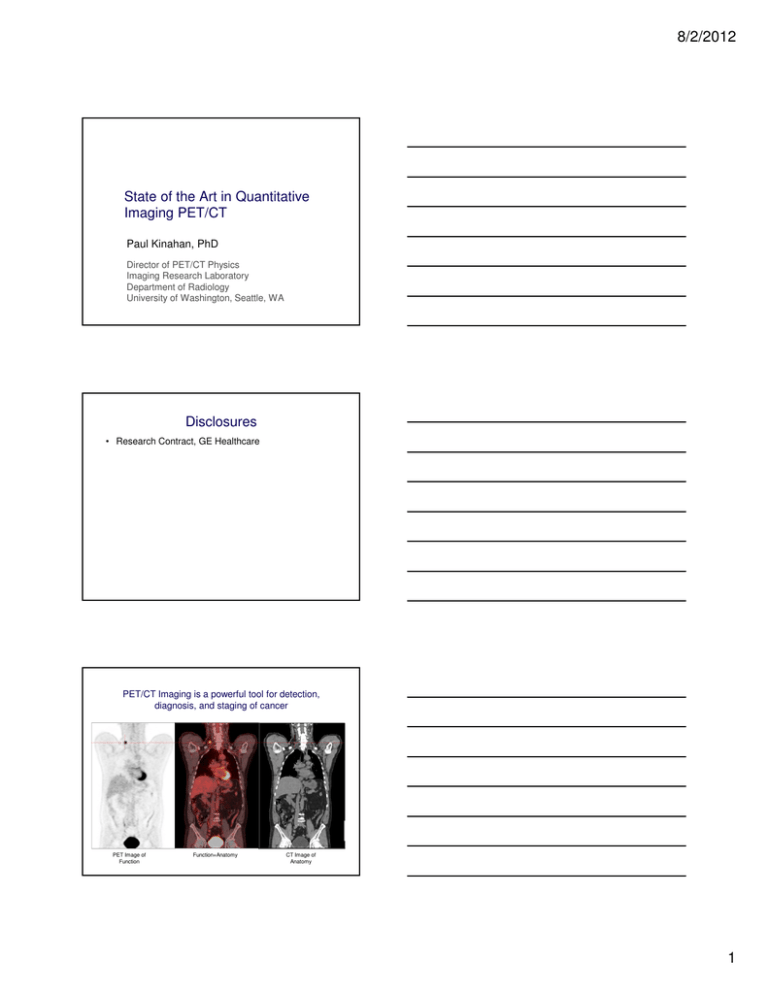
8/2/2012 State of the Art in Quantitative Imaging PET/CT Paul Kinahan, PhD Director of PET/CT Physics Imaging Research Laboratory Department of Radiology University of Washington, Seattle, WA Disclosures • Research Contract, GE Healthcare PET/CT Imaging is a powerful tool for detection, diagnosis, and staging of cancer PET Image of Function Function+Anatomy CT Image of Anatomy 1 8/2/2012 Clinical Applications IMV 2008 PET Imaging Market Summary Report Diagnostic Accuracy of PET/CT exceeds CT or PET only Weber et al. Nature Reviews Clinical Oncology 2008 Quantitative imaging can characterize hallmarks of disease and response to therapy Response to therapy of liver met GIST short term drivers • Clinical research, Clinical trials, and Drug discovery • New molecular diagnostic agents • Assessing individual response to therapy • SUVs are now routinely reported, and are asked for, by referring physicians increasing volume CT PET/CT Pretherapy 1 wk imatinib therapy PET SUV: 5 to 1.8 Castell and Cook, British J Cancer 2008 6 2 8/2/2012 Quantitative Imaging Definitions • A biomarker is an objectively measured indicator of biological/pathobiological process or pharmacologic response to treatment • Qualified biomarker: A disease-related biomarker linked by graded evidence to biological and clinical endpoints and dependent upon the intended use • Imaging biomarker: a number, set of numbers, or classification derived from an image (in general imaging biomarkers are not surrogate endpoints) • Validated assay: An assay (i.e. quantitative imaging) that has documented performance characteristics showing suitability for the intended applications – needed for a qualified biomarker Biomarkers Definitions Working Group. Clin Pharmacol Ther 2001;69(3):89–95. Quantitative Imaging Requirements • • • • Prior studies that measure variance Defined protocols Monitoring of protocols Calibration and QA/QC procedures to ensure variance stays within assumed range • Optional: Techniques and procedures that improve the measurement accuracy The Imaging Chain • For quantitative imaging, each component of the imaging chain requires – Quality Assurance (i.e protocol) – Quality Control (checking what actually happened) • Outline for all imaging methods: imaging physics patient status scan protocol processing & reconstruction analysis methods final accuracy & precision calibration 3 8/2/2012 PET Scanning Process Patient preparation Image reconstruction Scan acquisition Image analysis Image interpretation SUV measure Typical PET/CT Scan Protocol 1. Scout scan (5-10 sec) 2. Selection of scan region CT PET Scout scan image 3. Helical CT (30 sec) 4. Whole-body PET (15-30 min) CT PET CT PET Sources of Error in SUV Values SUV = Standardized Uptake Value SUV = PETROI DINJ ′ /V′ PET = measured PET activity concentration D' = decay-corrected injected dose V' = surrogate for volume of distribution It is important to minimize SUV errors for serial (e.g. response to Rx) or multi-center studies Some potential sources of error are: • High blood glucose levels • Variations in dose uptake time • Uncalibrated clocks (including scanner) and cross calibration of scanner with dose calibrator • Errors in radioactive dose assay • Variations in image reconstruction and other processing protocols and parameters • Variations in images analysis methods: E.g. how ROIs are drawn and whether max or mean SUV values are reported 4 8/2/2012 Instrumentation Chain for FDG-PET scanner units kBq/ml SUVs pre- and post injection assays patient weight (& height) PET scanner scanner global calibration factor dose calibrator decay corrected net activity 9.6 mCi Error Propagation in PET Imaging imaging physics patient status scan protocol data processing analysis methods accuracy & precision of PET SUVs calibration Kinahan and Fletcher, Sem US, CT, MR 2010 Estimate Source data Single-center best case: 10% Single-center, typical?: 10-18% Multi-center, best case: 15-20% Multi-center, typical: 15-50+% e.g. Minn 1999, Weber 2000 Velasquez 2009, (45% Eikman) Velasquez 2009 Fahey 2009, Doot 2010, 14 Impact of measurement error on power/sample size Sample Size power = 80% significance = 0.05 40% error 30 % 20% Sample size increases as error increases 10% True Effect Size (%) Doot et al., Acad Rad 2012 15 5 8/2/2012 Impact of measurement error and sensitivity to true change on sample size Trial Scenario error # of patients Single site 10% 12 Multi-center (good calibration) 20% 42 Multi-center (poor calibration) 40% 158 effect size = 20% power = 80% significance = 0.05 16 Doot et al., Acad Rad 2012 PET Technology Innovations First coincidence positron imaging system 1975 1989 1991 1998 2005 2006 2008 PETT III whole-body 3D PET PET/CT respiratory PET/MR imaging gating time-offlight 2,500,000 Procedures/yr 2,000,000 ? 100% Procedures/yr PET/CT % of Sales 80% 1,500,000 60% 1,000,000 40% 500,000 20% 0 1998 2000 2002 2004 2006 % scanners 1953 0% 2008 Recent PET Technology Innovations • Respiratory motion compensation • Time of flight imaging • Advanced modeling of PET physics in image reconstruction • Extended axial field of view • Cost effective PET/CT scanners • New detector systems • PET/MR scanners • CT dose reduction methods 6 8/2/2012 Clinical PET scanners are a moving target Different reconstruction methods on the same PET/CT scanner Modified NEMA NU-2 IQ phantom Recovery coefficient 1.5 VOI & EANM VOI & PSF+TOF M AX & EANM MAX & PSF+ TOF 1.25 1 0.75 • Hot sphere diameters of 10, 13, 17, 22, 28, and 37-mm • Target/background ratio 4:1 0.5 0.25 0.1 1 10 100 Sphere volume (mL) Courtesy Ronald Boellaard 19 Challenges with Implementing Quantitative Imaging - Industry • There is significant variability between manufacturers in allowable scan protocols and trade-offs in image quality • There are few, if any, tests of the quantitative accuracy of images transferred between display/analysis systems • Due to several reasons: – Lack of standards by which vendors can assure compliance of acquisition/processing algorithms – Lack of convincing (to vendors) evidence of a market for quantitative imaging Challenges with Implementing Quantitative Imaging - Imaging Sites • There is a tension with imaging protocols suitable for current clinical practice • Often there is no standard clinical practice • E.g. when 'standard of care' is requested, any of the following may occur: – – – – – – Blood glucose levels may be ignored or not reported Tracer uptake time may vary PET images may be acquired in 2D or 3D PET images may be reconstructed with different algorithms PET images may be reconstructed with different smoothing SUVs may be measured differently and/or on different platforms – May do an MR or CT scan instead 7 8/2/2012 What do we do? • There are three main routes of action 1. Accreditation authorities 2. Standards definitions and harmonization initiatives 3. Calibration methods and/or phantoms Quantitative PET/CT Standards and/or Accreditation Bodies in the US • • • • • • • • NEMA/MITA Standards AAPM ANSI (DICOM) Clinical Research Organizations ACR Clinical IAC PET Core Labs (CALGB, DFCI, ...) ACRIN • SNM • FDA • NRC (DOE), DOT Accreditation Clinical Trials Regulatory Quantitative Imaging Initiatives • ACRIN Centers of Quantitative Imaging Excellence (CQIE) • Quantitative Imaging Biomarkers Alliance (QIBA) – Now includes the Uniform Protocols for Imaging in Clinical Trials (UPICT) • Quantitative Imaging Network (QIN) • American Association of Physicists in Medicine Task Group 145 (Quantitative Imaging for PET) • Reconstruction Harmonization Project (ACRIN / SNM-CTN / QIN / QIBA) • EANM and EORTC initiatives 8 8/2/2012 Calibration phantoms for Quantitative PET/CT Standards and/or Accreditation • Uniform Cylinder (used by ACRIN and many others) • ACR PET phantom • NEMA NU-2 Image Quality (IQ) phantom • Modified NEMA Image Quality (IQ) phantom • SNM CTN phantom • Cross Calibration Phantom with NIST-traceable 68Ge standard for Dose Calibrator • Digital reference object Multi-center repeated PET/CT scans Modified NEMA NU-2 IQ phantom • Values for 11 scanners at 8 academic imaging centers. • Results should be independent of sphere diameter. • Hot sphere diameters of 10, 13, 17, 22, 28, and 37-mm • Target/background ratio 4:1 Doot PhD Thesis 2008, Kinahan et al 2008 SNM PET image reconstruction harmonization harmonized and optimized reconstruction Recovery coefficient (measured / true) 100 % range for harmonized reconstruction current range for PET scanners 0 0 Diameter (cm) 4 9 8/2/2012 PET Digital Reference Object (DRO) • The DRO is a synthetically generated set of DICOM image files of known voxel values for PET and CT • Intended to test computation of SUVs and ROIs • Version 1 released 10/31/2011 • More info at depts.washington.edu/petctdro PET Digital Reference Object (DRO) PET/CT image generation Scanner models 1..m Manufacturer A Scanner models Manufacturer B PET/CT DRO DICOM files Scanner models Manufacturer C Other Manufacturers / sources of PET SUV data PET DICOM files PET/CT image SUV and ROI measurement Display Station(s) Vendor 1 Display Station(s) Vendor 2 Display Station(s) Vendor 3 Display Station(s) Vendor n PET Digital Reference Object (DRO) PET (emission) coronal section transaxial section CT (transmission) ROI based analysis 10 8/2/2012 Results: 13 sites, 20 different display systems blue = okay, yellow = ?, pink = borderline, red = wrong different sites/systems results for each of the 6 ROIs CONCLUSION State of the art: Quantitative imaging requirements • Test-retest studies in the literature demonstrate that quantitative image acquisition protocols are possible • To enable quantitative image acquisition protocols we need – Standards by which users can assure compliance – The above standards can be provided by standardized methods, e.g. QIBA Profiles and UPICT Protocols – Education for (and adoption by) radiologists, if they are to remain in the image processing chain 11 8/2/2012 Extra slides Effects of Attenuation: Patient Study reduced mediastinal uptake 'hot' lungs Nonuniform liver Enhanced skin uptake PET: without attenuation correction PET: with attenuation correction (accurate) CT image (accurate) Attenuation, and errors in attenuation correction, can dominate image quality Typical Radiation Doses 12 8/2/2012 CT-based Attenuation Correction • • • The mass-attenuation coefficient (µ/ρ) is similar for all non-bone materials since Compton scatter dominates for these materials Bone has a higher photoelectric absorption cross-section due to presence of calcium Can use two different scaling factors: one for bone and one for everything else 100.00 Bone, Cortical Muscle, Skeletal Air µ/ρ 10.00 1.00 bone 0.10 everything else 0.01 70 10 100 511 keV 1000 CT-based Attenuation Correction 0.20 0.15 (µ ) linear attenuation coeffcient • Bi-linear scaling methods apply different scale factors for bone and nonbone materials • Should be calibrated for every kVp and/or contrast agent 0.10 water-bone mixture air-water mixture 0.05 0.00 air -1000 soft tissue -500 0 dense bone 500 1000 1500 CT Hounsfield Units PET/CT Anatomy All 3 (couch, CT and PET) must be in accurate alignment 13 8/2/2012 Data Flow and Processing • CT images are also used for calibration (attenuation correction) of the PET data X-ray acquisition PET Emission Acquisition • • Anatomical (CT) Reconstruction Smooth to PET Resolution Translate CT to PET Energy (511 keV) Attenuation Correct PET Emission Data Functional (PET) Reconstruction CT Image PET Image Display of PET and CT DICOM image stacks Note that images are not really fused, but are displayed as fused or sideby-side with linked cursors Note also that the CT is used for attenuation correction, thus a significant potential for error Respiratory Artifacts: Propagation of CT breathing artifacts via CT-based attenuation correction Attenuation artifacts can dominate true tracer uptake values What Do PET Scans Measure? • • • If everything goes well, the role of the PET scanner is to measure the radioactivity per unit volume Typically measured as kBq/ml or υCi/ml Start with a simple example: inject 10 mCi = 370 MBq 70 kg water = 70 L suppose there is a very small object that takes up 5x the local concentration, so its concentration = 26.5 kBq/ml concentration = 370,000 kBq / 70,000 ml = 5.3 kBq/ml 14 8/2/2012 What if there are different activities or distribution volumes? • Injecting different amounts or changing the volume will change the concentration concentration = 5.3 kBq/ml inject 10 mCi = 370 MBq 26.5 kBq/ml The hot spot has different uptake values in kBq/ml even though it has the same relative uptake compared to background concentration = 2.8 kBq/ml inject 5 mCi = 185 MBq 13.3 kBq/ml concentration = 10.6 kBq/ml inject 10 mCi = 370 MBq 53.0 kBq/ml 35 kg = 35 L Standardized uptake values (SUVs) Normalize by amounts injected per volume (i.e. weight) to get the same relative distribution with SUV = 1.0 for a uniform distribution SUV = 5.3 kBq/ml / (370MBq/70 Kg) = 1.0 gm/ml inject 10 mCi = 370 MBq SUV = 5.0 The hot spot now has the same SUV uptake values independent in activity injected or volume of distribution (i.e. patient size) SUV = 1.0 gm/ml inject 5 mCi = 185 MBq SUV = 5.0 SUV = 1.0 gm/ml inject 10 mCi = 370 MBq SUV = 5.0 35 kg = 35 L Resolution Effects • Modified NEMA NU-2 Image Quality Phantom (30 cm x 23 cm cross section) • Sphere diameters:1.0, 1.3, 1.7, 2.2, 2.8, 3.7 cm • 4:1 target:background ratio and typical patient activity • RC = measured / true Recovery Coef f cient ( RC) wit h 2D FBP 1 0 .8 RC • 0 .6 0 .4 Mean RC f or ROI 0 .2 Max RC f or ROI 0 0 1 2 3 4 Diamet er (cm) 15 8/2/2012 Variations in resolution loss vs. size and smoothing OSEM Mean FBP Max Incr smoothing Question What is the goal of a combined PET/CT scanner? 1. Accurate attenuation correction 2. Accurate image alignment 3. Revitalize nuclear medicine 4. Job security for physicists PET Technology Innovations 1989 1991 1998 2005 2006 2008 PETT III whole-body 3D PET PET/CT respiratory PET/MR imaging gating time-offlight 2,500,000 2,000,000 100% Procedures/yr PET/CT % of Sales 80% 1,500,000 60% 1,000,000 40% 500,000 20% 0 1998 2000 2002 2004 2006 % scanners First coincidence positron imaging system 1975 Procedures/yr 1953 0% 2008 16
